SanDisk SDSDH-1024 Product Manual - Page 27
Bus Operating Conditions, Bus Signal Line Load
 |
UPC - 710348911073
View all SanDisk SDSDH-1024 manuals
Add to My Manuals
Save this manual to your list of manuals |
Page 27 highlights
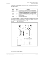
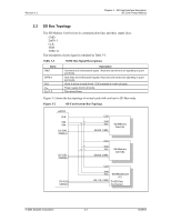
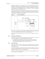
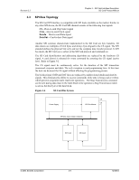
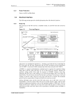
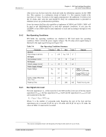
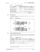
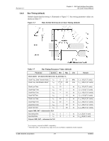
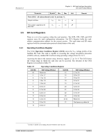
Revision 2.2 Chapter 3 - SD Card Interface Description SD Card Product Manual 3.4.2 After power up, the host starts the clock and sends the initializing sequence on the CMD line. This sequence is a contiguous stream of logical '1's. The sequence length is the maximum of 1msec, 74 clocks or the supply-ramp-up-time; the additional 10 clocks (over the 64 clocks after what the card should be ready for communication) is provided to eliminate power-up synchronization problems. Every bus master shall have the capability to implement ACMD41 and CMD1. CMD1 will be used to ask MultiMediaCards to send their operation conditions. In any case the ACMD41 or the CMD1 shall be send separately to each card accessing it through its own CMD line. Bus Operating Conditions SPI Mode bus operating conditions are identical to SD Card mode bus operating conditions. Table 3-4 lists the power supply voltages. The CS (chip select) signal timing is identical to the input signal timing (see Figure 3-8). Table 3-4 Bus Operating Conditions Summary Parameter General Peak voltage on all lines All Inputs Input Leakage Current All Outputs Output Leakage Current Power Supply Voltage7 Supply Voltage Supply voltage differentials (VSS1, VSS2) Power-up Time Symbol Min Max Unit --- -0.3 VDD + 0.3 V Remark --- -10 10 uA --- -10 10 uA VDD 2.0 3.6 V CMD0, 15, 55, ACMD41 commands VDD 2.7 3.6 V Except CMD0, 15, 55, ACMD41 commands --- -0.3 0.3 V --- --- 250 mS From 0 V to VDD min. 3.4.3 Bus Signal Line Load The total capacitance, CL, of the clock line in the SD Card bus is the sum of the bus-master capacitance (CHOST), the bus capacitance (CBUS) itself and the capacitance (CCARD) of each card connected to this line: CL = CHOST + CBUS + N*CCARD Where N is the number of connected cards. Requiring the sum of the host and bus capacitances not to exceed 30 pF for up to 10 cards, and 40 pF for up to 30 cards, the values in Table 3-4 must not be exceeded. 7 The current consumption of any card during the power-up procedure must not exceed 10 mA. © 2004 SanDisk Corporation 3-7 12/08/04
-
 1
1 -
2
-
3
-
4
-
5
-
6
-
7
-
8
-
9
-
10
-
11
-
12
-
13
-
14
-
15
-
16
-
17
-
18
-
19
-
20
-
21
-
 22
22 -
 23
23 -
 24
24 -
 25
25 -
 26
26 -
 27
27 -
 28
28 -
 29
29 -
 30
30 -
 31
31 -
 32
32 -
33
-
34
-
35
-
36
-
37
-
38
-
39
-
40
-
41
-
42
-
43
-
44
-
45
-
46
-
47
-
48
-
49
-
50
-
51
-
52
-
53
-
54
-
55
-
56
-
57
-
58
-
59
-
60
-
61
-
62
-
63
-
64
-
65
-
66
-
67
-
68
-
69
-
70
-
71
-
72
-
73
-
74
-
75
-
76
-
77
-
78
-
79
-
80
-
81
-
82
-
83
-
84
-
85
-
86
-
87
-
88
-
89
-
90
-
91
-
92
-
93
-
94
-
95
-
96
-
97
-
98
-
99
-
100
-
101
-
102
-
103
-
104
-
105
-
106
-
107
-
108
-
109
-
110
-
111
-
112
-
113
-
114
-
115
-
116
-
117
-
118
-
119
-
120
-
121
-
122
-
123
 |
 |
