Sony SRR4 Product Manual (SRMASTER: SRR4 Operation Manual) - Page 10
Names of Parts, Overall View, Left Side View
 |
View all Sony SRR4 manuals
Add to My Manuals
Save this manual to your list of manuals |
Page 10 highlights
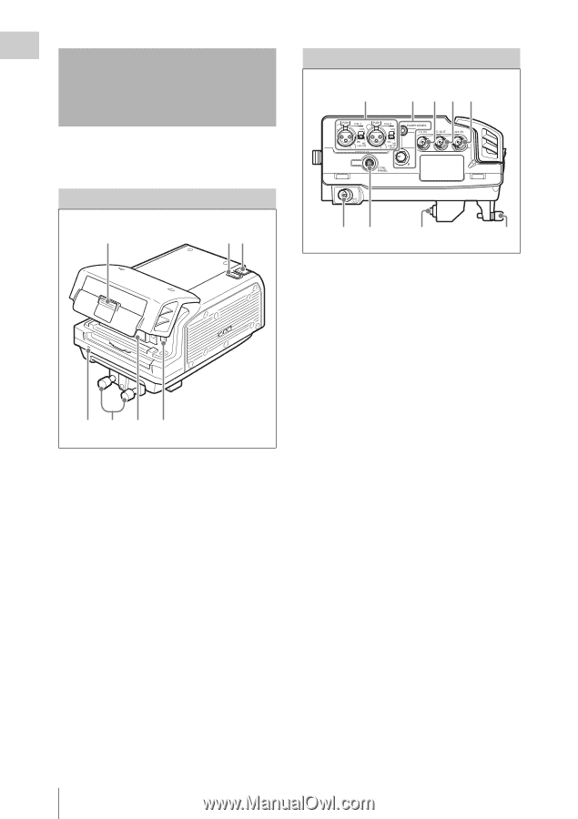
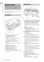
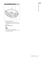
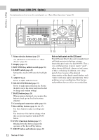
Chapter 1 Overview Names of Parts Left Side View 1 2 345 For detailed information on functions and usage, see the pages indicated in brackets. Overall View 1 23 765 4 1. Lid open/close button (page 22) 2. Tally indicator (page 22) Lights up during recording. Flashes as a warning indication when an error or problem has occurred. 3. POWER (power supply) indicator (page 21) Lights up in green when power to the unit is on. 4. EJECT button (page 23) 5. SRMemory card slot (page 22) 6. Docking screws (page 18) 7. LID LOCK indicator (page 22) Lights up in orange when an SRMemory card is mounted. 10 Names of Parts 98 7 6 1. AUDIO INPUT CH-1, CH-2 (analog audio input channel 1, 2) connectors (3-pin XLR, female) and input selection switches Set the input selection switches as follows, depending on the type and level of the input audio. LINE: For line input MIC: For microphone input MIC +48V ON: For input from microphones with external power supply 2. EARPHONES jack (stereo mini jack) and LEVEL knob Adjusts the audio level. A warning/alarm tone is also output via this jack when an error is detected. 3. TC IN (time code input) connector (BNC) Connect to the time code output connector of an external device such as a time code generator or VTR. Use this connector when locking the internal time code generator to external time code. 4. TC OUT (time code output) connector (BNC) Connect to the time code input connector of an external device such as a time code reader or VTR. Signal is supplied according to setting made from TC Setup menu, OTHERS >TC OUT. (see page 41) 5. AUX IN (for future use) 6. Docking screws (page 18) 7. CAMERA connector (page 17) 8. CTRL PANEL (Control Panel) connector (page 16) 9. AUX OUT connector (for future use)
-
 1
1 -
2
-
3
-
4
-
 5
5 -
 6
6 -
 7
7 -
 8
8 -
 9
9 -
 10
10 -
 11
11 -
 12
12 -
 13
13 -
 14
14 -
 15
15 -
16
-
17
-
18
-
19
-
20
-
21
-
22
-
23
-
24
-
25
-
26
-
27
-
28
-
29
-
30
-
31
-
32
-
33
-
34
-
35
-
36
-
37
-
38
-
39
-
40
-
41
-
42
-
43
-
44
-
45
-
46
-
47
-
48
-
49
-
50
-
51
-
52
-
53
-
54
-
55
-
56
-
57
-
58
-
59
-
60
-
61
 |
 |