Sony SRR4 Product Manual (SRMASTER: SRR4 Operation Manual) - Page 13
Display, Audio level meters, Operation status and warning indicator, SRMemory card icon indications
 |
View all Sony SRR4 manuals
Add to My Manuals
Save this manual to your list of manuals |
Page 13 highlights
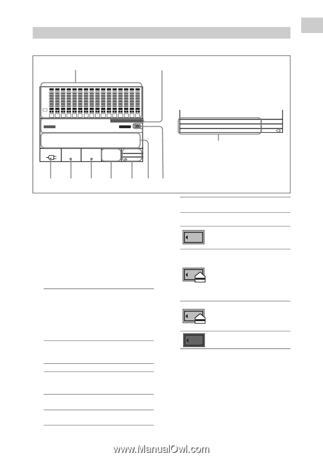
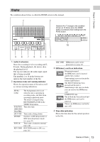
Chapter 1 Overview Display The condition shown below is called the HOME screen in this manual. 1 2 dB SDI SDI SDI SDI SDI SDI SDI SDI SDI SDI SDI SDI SDI SDI SDI SDI 0 -10 -20 -30 -60 EE EMP EMP EMP EMP EMP EMP EMP EMP EMP EMP EMP EMP EMP EMP EMP EMP LR LR LR LR LR LR LR LR LR LR LR LR LR LR LR LR 1 2 3 4 5 6 7 8 9 10 11 12 13 14 15 16 STOP SR-R4:CAM TCG KEYINHI RECINHI 00 H 00 M 00 S 00 F 16.5V REMAIN ENCODE F65RAW STANDARD 23.98P 10min LOCAL EE 21:46 Sections 4 to 7 change to the condition shown as 10 below when the HOME button is pressed while holding down the FUNC button. 00 H 00 M 00 S 00 F SYS: F65RAW 23.98P EMCODE: STANDARD PB: F65RAW 23.98P LOCAL --- 16.5V 10 9 8 7 6 5 43 1. Audio level meters Show the recording level in recording and EE mode. During playback, the meters show the playback level. The top row indicates the audio input signal that is being recorded. The numbers 1 to 16 in the bottom row indicate the track number of the file. 2. Operation status and warning indicator Shows the operation status of the unit as well as various warning indications. SR-R4: The background color is red CAM when the unit is operating in recording mode, and blue when operating in playback mode. The mode is changed using RECORDER/PLAYER in the VIDEO Setup menu. TCR/TCG/ Time data type. UBR/UBG/ TM1/TM2 LTC/VITC Time code is being shown. DF/NDF System is in DF (drop-frame) or NDF (non-drop frame) mode. (see page 41) EXT-LK Time code is locked to external time code. KEY INHI KEY INHI switch is ON. (see page 26) REC INHI SRMemory card is writeprotected. (see page 23) 3. SRMemory card icon indications Mounting/mounted An SRMemory card is inserted and the lid is locked. Unmounting (cursor section in the bottom right flashes) The EJECT button has been pressed and the unit is transitioning to the state in which you can remove the SRMemory card. UNMOUNT state The lid lock has been released and the SRMemory card can be removed. There is no SRMemory card in the unit. (off) 4. Time data indication Shows the time data for the current position in the file. Names of Parts 13
-
 1
1 -
2
-
3
-
4
-
5
-
6
-
7
-
 8
8 -
 9
9 -
 10
10 -
 11
11 -
 12
12 -
 13
13 -
 14
14 -
 15
15 -
 16
16 -
 17
17 -
 18
18 -
19
-
20
-
21
-
22
-
23
-
24
-
25
-
26
-
27
-
28
-
29
-
30
-
31
-
32
-
33
-
34
-
35
-
36
-
37
-
38
-
39
-
40
-
41
-
42
-
43
-
44
-
45
-
46
-
47
-
48
-
49
-
50
-
51
-
52
-
53
-
54
-
55
-
56
-
57
-
58
-
59
-
60
-
61
 |
 |