Sony SRR4 Product Manual (SRMASTER: SRR4 Operation Manual) - Page 48
Appendix, Maintenance and Inspections, Note About the CAMERA Connector, Maintenance and, Inspections
 |
View all Sony SRR4 manuals
Add to My Manuals
Save this manual to your list of manuals |
Page 48 highlights
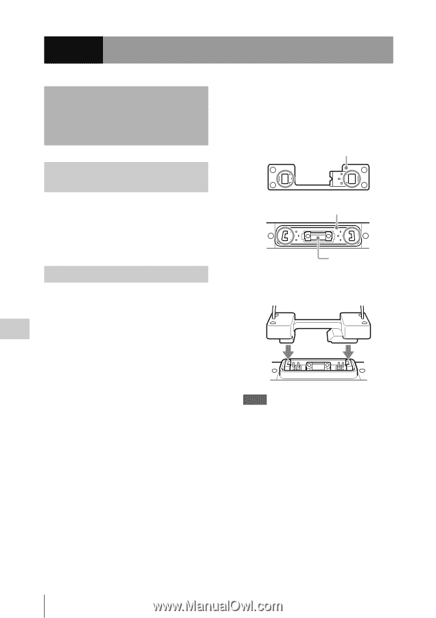
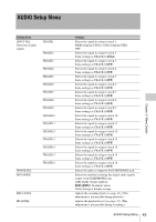
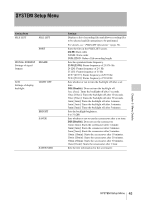
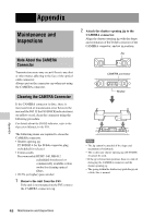
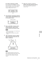
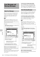
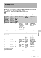
Appendix Maintenance and Inspections Note About the CAMERA Connector Transmission errors may occur if there is any dust or other matter adhering to the face of the optical cable connector. Always put on the connector cap when not using the CAMERA connector. Cleaning the CAMERA Connector If the CAMERA connector is dirty, there is increased risk of transmission error between the unit and the F65. If the F65 DOCK indicator turns on yellow or red, clean the connector using the following procedure. For details about the DOCK indicator, refer to the Operation Manual for the F65. The following items are required to clean the CAMERA connector. • Shutter opening jig JT-FODSP-4 for the D-Sub connector plug (scheduled for release) • Cotton swabs Recommended: HUBY-340, BB-012 (scheduled for release) or commercially available cotton swabs for cleaning optical fibers. • 99.5% (or higher) pure alcohol 1 Remove the unit from the F65. If the unit is not mounted on the F65, remove the CAMERA connector cap. 2 Attach the shutter opening jig to the CAMERA connector. Align the shutter opening jig with the shape and orientation of the D-Sub connector of the CAMERA connector, and set in position. Jig CAMERA connector Shutter m Notes • The jig cannot be attached if the shape and orientation is backwards. • The socket-side shutter opening jig (JT-FODSS- 4) cannot be used. • If the jig is forced into position, there is a risk of damaging the CAMERA connector and the shutter opening jig. • The spring within the shutter may push the jig out a little; this is normal. Appendix 48 Maintenance and Inspections
-
 1
1 -
2
-
3
-
4
-
5
-
6
-
7
-
8
-
9
-
10
-
11
-
12
-
13
-
14
-
15
-
16
-
17
-
18
-
19
-
20
-
21
-
22
-
23
-
24
-
25
-
26
-
27
-
28
-
29
-
30
-
31
-
32
-
33
-
34
-
35
-
36
-
37
-
38
-
39
-
40
-
41
-
42
-
 43
43 -
 44
44 -
 45
45 -
 46
46 -
 47
47 -
 48
48 -
 49
49 -
 50
50 -
 51
51 -
 52
52 -
 53
53 -
54
-
55
-
56
-
57
-
58
-
59
-
60
-
61
 |
 |