Sony SRR4 Product Manual (SRMASTER: SRR4 Operation Manual) - Page 21
Turn Power On, To power up the unit, Checking the power/voltage
 |
View all Sony SRR4 manuals
Add to My Manuals
Save this manual to your list of manuals |
Page 21 highlights
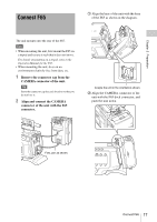
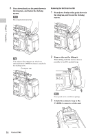
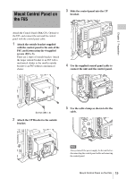
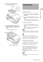
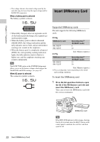
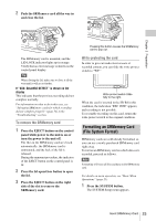
2 Attach the supplied BKP spacer. The S symbol must face up. S symbols Turn Power On Chapter 2 Preparation 3 Attach the BKP-L551 using the screw holes labeled with an S symbol, and fasten. BKP-L551 fastening L screws To accessory BKP-L551 fastening L wrench To power up the unit 1 Press the power switch on the SR-R4 on the ? side. 2 Set the F65 POWER OFF/ON switch to ON. The power comes on together with the F65 and the POWER indicator lights up in green. To power down the unit 1 Set the F65 POWER OFF/ON switch to OFF. The power is turned off together with the F65 and the POWER indicator goes out. Note To prevent the risk of data corruption, do not interrupt the F65 DC IN power supply while the SR-R4 is turned on. Tip If power is turned off while an SRMemory card is mounted, the unit will not power down immediately, to protect the data on the card. The SRMemory card will be unmounted first, and then the unit powers down. Checking the power/voltage The indication at the bottom left of the control panel display serves to verify the battery status or the voltage of the external power supply. However, this indication is not based on the actual connection condition but on the setting made under SYSTEM Setup > BATTERY > DCIN TYPE. (see page 46) Set DCIN TYPE to match the power supply used by the F65. Tips • When signal format is shown, the indication appears at bottom right. Turn Power On 21
-
 1
1 -
2
-
3
-
4
-
5
-
6
-
7
-
8
-
9
-
10
-
11
-
12
-
13
-
14
-
15
-
 16
16 -
 17
17 -
 18
18 -
 19
19 -
 20
20 -
 21
21 -
 22
22 -
 23
23 -
 24
24 -
 25
25 -
 26
26 -
27
-
28
-
29
-
30
-
31
-
32
-
33
-
34
-
35
-
36
-
37
-
38
-
39
-
40
-
41
-
42
-
43
-
44
-
45
-
46
-
47
-
48
-
49
-
50
-
51
-
52
-
53
-
54
-
55
-
56
-
57
-
58
-
59
-
60
-
61
 |
 |
