TP-Link TL-SG3216 TL-SG3216 V1 User Guide - Page 104
Multicast VLAN
 |
View all TP-Link TL-SG3216 manuals
Add to My Manuals
Save this manual to your list of manuals |
Page 104 highlights
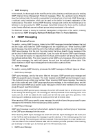
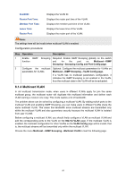
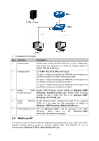
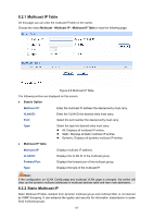
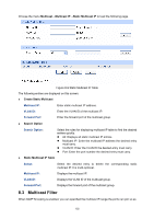
VLAN ID: Router Port Time: Member Port Time: Leave Time: Router Port: Displays the VLAN ID. Displays the router port time of the VLAN. Displays the member port time of the VLAN. Displays the leave time of the VLAN. Displays the router port of the VLAN. Note: The settings here will be invalid when multicast VLAN is enabled Configuration procedure: Step Operation Description 1 Enable IGMP Snooping Required. Enable IGMP Snooping globally on the switch function and for the port on Multicast→IGMP Snooping→Snooping Config and Port Config page. 2 Configure the multicast Optional. Configure the multicast parameters for VLANs on parameters for VLANs Multicast→IGMP Snooping→VLAN Config page. If a VLAN has no multicast parameters configuration, it indicates the IGMP Snooping is not enabled in the VLAN, thus the multicast data in the VLAN will be broadcasted. 8.1.4 Multicast VLAN In old multicast transmission mode, when users in different VLANs apply for join the same multicast group, the multicast router will duplicate this multicast information and deliver each VLAN owning a receiver one copy. This mode wastes a lot of bandwidth. The problem above can be solved by configuring a multicast VLAN. By adding switch ports to the multicast VLAN and enabling IGMP Snooping, you can make users in different VLANs share the same multicast VLAN. This saves the bandwidth since multicast streams are transmitted only within the multicast VLAN and also guarantees security because the multicast VLAN is isolated from user VLANS. Before configuring a multicast VLAN, you should firstly configure a VLAN as multicast VLAN and add the corresponding ports to the VLAN on the 802.1Q VLAN page. If the multicast VLAN is enabled, the multicast configuration for other VLANs on the VLAN Config page will be invalid, that is, the multicast streams will be transmitted only within the multicast VLAN. Choose the menu Multicast→IGMP Snooping→Multicast VLAN to load the following page. 97
-
 1
1 -
2
-
3
-
4
-
5
-
6
-
7
-
8
-
9
-
10
-
11
-
12
-
13
-
14
-
15
-
16
-
17
-
18
-
19
-
20
-
21
-
22
-
23
-
24
-
25
-
26
-
27
-
28
-
29
-
30
-
31
-
32
-
33
-
34
-
35
-
36
-
37
-
38
-
39
-
40
-
41
-
42
-
43
-
44
-
45
-
46
-
47
-
48
-
49
-
50
-
51
-
52
-
53
-
54
-
55
-
56
-
57
-
58
-
59
-
60
-
61
-
62
-
63
-
64
-
65
-
66
-
67
-
68
-
69
-
70
-
71
-
72
-
73
-
74
-
75
-
76
-
77
-
78
-
79
-
80
-
81
-
82
-
83
-
84
-
85
-
86
-
87
-
88
-
89
-
90
-
91
-
92
-
93
-
94
-
95
-
96
-
97
-
98
-
 99
99 -
 100
100 -
 101
101 -
 102
102 -
 103
103 -
 104
104 -
 105
105 -
 106
106 -
 107
107 -
 108
108 -
 109
109 -
110
-
111
-
112
-
113
-
114
-
115
-
116
-
117
-
118
-
119
-
120
-
121
-
122
-
123
-
124
-
125
-
126
-
127
-
128
-
129
-
130
-
131
-
132
-
133
-
134
-
135
-
136
-
137
-
138
-
139
-
140
-
141
-
142
-
143
-
144
-
145
-
146
-
147
-
148
-
149
-
150
-
151
-
152
-
153
-
154
-
155
-
156
-
157
-
158
-
159
-
160
-
161
-
162
-
163
-
164
-
165
-
166
-
167
-
168
-
169
-
170
-
171
-
172
-
173
-
174
-
175
-
176
-
177
-
178
-
179
-
180
-
181
-
182
-
183
-
184
-
185
-
186
-
187
-
188
-
189
-
190
-
191
-
192
-
193
-
194
-
195
-
196
-
197
-
198
-
199
-
200
-
201
-
202
-
203
-
204
-
205
-
206
-
207
-
208
-
209
-
210
-
211
-
212
-
213
-
214
-
215
-
216
-
217
-
218
-
219
-
220
-
221
-
222
-
223
-
224
-
225
-
226
-
227
-
228
-
229
-
230
-
231
-
232
 |
 |