TP-Link TL-SG3216 TL-SG3216 V1 User Guide - Page 205
Log Table, 2.2 Local Log
 |
View all TP-Link TL-SG3216 manuals
Add to My Manuals
Save this manual to your list of manuals |
Page 205 highlights
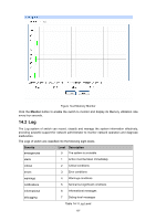
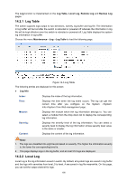
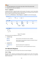
The Log function is implemented on the Log Table, Local Log, Remote Log and Backup Log pages. 14.2.1 Log Table The switch supports logs output to two directions, namely, log buffer and log file. The information in log buffer will be lost after the switch is rebooted or powered off whereas the information in log file will be kept effective even the switch is rebooted or powered off. Log Table displays the system log information in log buffer. Choose the menu Maintenance→Log→Log Table to load the following page. Figure 14-3 Log Table The following entries are displayed on this screen: ¾ Log Info Index: Displays the index of the log information. Time: Displays the time when the log event occurs. The log can get the correct time after you configure on the System ->System Info->System Time Web management page. Module: Displays the module which the log information belongs to. You can select a module from the drop-down list to display the corresponding log information. Severity: Displays the severity level of the log information. You can select a severity level to display the log information whose severity level value is the same or smaller. Content: Displays the content of the log information. Note: 1. The logs are classified into eight levels based on severity. The higher the information severity is, the lower the corresponding level is. 2. This page displays logs in the log buffer, and at most 512 logs are displayed. 14.2.2 Local Log Local Log is the log information saved in switch. By default, all system logs are saved in log buffer and the logs with severities from level_0 to level_4 are saved in log file meanwhile. On this page, you can set the output channel for logs. 198
-
 1
1 -
2
-
3
-
4
-
5
-
6
-
7
-
8
-
9
-
10
-
11
-
12
-
13
-
14
-
15
-
16
-
17
-
18
-
19
-
20
-
21
-
22
-
23
-
24
-
25
-
26
-
27
-
28
-
29
-
30
-
31
-
32
-
33
-
34
-
35
-
36
-
37
-
38
-
39
-
40
-
41
-
42
-
43
-
44
-
45
-
46
-
47
-
48
-
49
-
50
-
51
-
52
-
53
-
54
-
55
-
56
-
57
-
58
-
59
-
60
-
61
-
62
-
63
-
64
-
65
-
66
-
67
-
68
-
69
-
70
-
71
-
72
-
73
-
74
-
75
-
76
-
77
-
78
-
79
-
80
-
81
-
82
-
83
-
84
-
85
-
86
-
87
-
88
-
89
-
90
-
91
-
92
-
93
-
94
-
95
-
96
-
97
-
98
-
99
-
100
-
101
-
102
-
103
-
104
-
105
-
106
-
107
-
108
-
109
-
110
-
111
-
112
-
113
-
114
-
115
-
116
-
117
-
118
-
119
-
120
-
121
-
122
-
123
-
124
-
125
-
126
-
127
-
128
-
129
-
130
-
131
-
132
-
133
-
134
-
135
-
136
-
137
-
138
-
139
-
140
-
141
-
142
-
143
-
144
-
145
-
146
-
147
-
148
-
149
-
150
-
151
-
152
-
153
-
154
-
155
-
156
-
157
-
158
-
159
-
160
-
161
-
162
-
163
-
164
-
165
-
166
-
167
-
168
-
169
-
170
-
171
-
172
-
173
-
174
-
175
-
176
-
177
-
178
-
179
-
180
-
181
-
182
-
183
-
184
-
185
-
186
-
187
-
188
-
189
-
190
-
191
-
192
-
193
-
194
-
195
-
196
-
197
-
198
-
199
-
 200
200 -
 201
201 -
 202
202 -
 203
203 -
 204
204 -
 205
205 -
 206
206 -
 207
207 -
 208
208 -
 209
209 -
 210
210 -
211
-
212
-
213
-
214
-
215
-
216
-
217
-
218
-
219
-
220
-
221
-
222
-
223
-
224
-
225
-
226
-
227
-
228
-
229
-
230
-
231
-
232
 |
 |
