TP-Link TL-SG3216 TL-SG3216 V1 User Guide - Page 78
STP Timers, BPDU Comparing Principle in STP mode, STP Generation
 |
View all TP-Link TL-SG3216 manuals
Add to My Manuals
Save this manual to your list of manuals |
Page 78 highlights
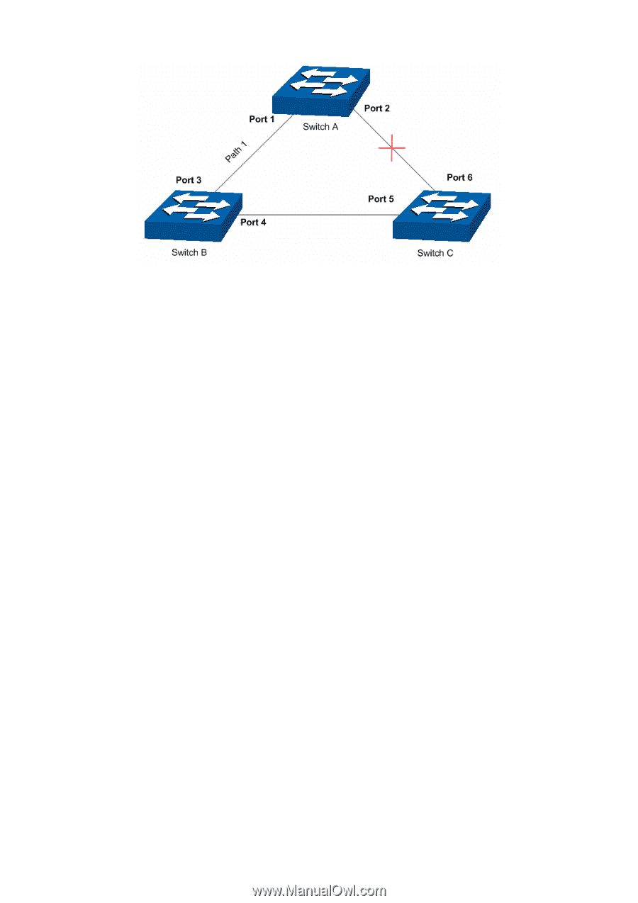
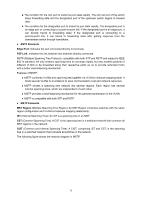
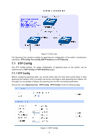
Figure 7-1 Basic STP diagram ¾ STP Timers Hello Time: Hello Time ranges from 1 to 10 seconds. It specifies the interval to send BPDU packets. It is used to test the links. Max. Age: Max. Age ranges from 6 to 40 seconds. It specifies the maximum time the switch can wait without receiving a BPDU before attempting to reconfigure. Forward Delay: Forward Delay ranges from 4 to 30 seconds. It specifies the time for the port to transit its state after the network topology is changed. When the STP regeneration caused by network malfunction occurs, the STP structure will get some corresponding change. However, as the new configuration BPDUs cannot be spread in the whole network at once, the temporal loop will occur if the port transits its state immediately. Therefore, STP adopts a state transit mechanism, that is, the new root port and the designated port begins to forward data after twice forward delay, which ensures the new configuration BPDUs are spread in the whole network. ¾ BPDU Comparing Principle in STP mode Assuming two BPDUs: BPDU X and BPDU Y If the root bridge ID of X is smaller than that of Y, X is superior to Y. If the root bridge ID of X equals that of Y, but the root path cost of X is smaller than that of Y, X is superior to Y. If the root bridge ID and the root path cost of X equal those of Y, but the bridge ID of X is smaller than that of Y, X is superior to Y. If the root bridge ID, the root path cost and bridge ID of X equal those of Y, but the port ID of X is smaller than that of Y, X is superior to Y. ¾ STP Generation z In the beginning In the beginning, each switch regards itself as the root, and generates a configuration BPDU for each port on it as a root, with the root path cost being 0, the ID of the designated bridge being that of the switch, and the designated port being itself. 71
-
 1
1 -
2
-
3
-
4
-
5
-
6
-
7
-
8
-
9
-
10
-
11
-
12
-
13
-
14
-
15
-
16
-
17
-
18
-
19
-
20
-
21
-
22
-
23
-
24
-
25
-
26
-
27
-
28
-
29
-
30
-
31
-
32
-
33
-
34
-
35
-
36
-
37
-
38
-
39
-
40
-
41
-
42
-
43
-
44
-
45
-
46
-
47
-
48
-
49
-
50
-
51
-
52
-
53
-
54
-
55
-
56
-
57
-
58
-
59
-
60
-
61
-
62
-
63
-
64
-
65
-
66
-
67
-
68
-
69
-
70
-
71
-
72
-
 73
73 -
 74
74 -
 75
75 -
 76
76 -
 77
77 -
 78
78 -
 79
79 -
 80
80 -
 81
81 -
 82
82 -
 83
83 -
84
-
85
-
86
-
87
-
88
-
89
-
90
-
91
-
92
-
93
-
94
-
95
-
96
-
97
-
98
-
99
-
100
-
101
-
102
-
103
-
104
-
105
-
106
-
107
-
108
-
109
-
110
-
111
-
112
-
113
-
114
-
115
-
116
-
117
-
118
-
119
-
120
-
121
-
122
-
123
-
124
-
125
-
126
-
127
-
128
-
129
-
130
-
131
-
132
-
133
-
134
-
135
-
136
-
137
-
138
-
139
-
140
-
141
-
142
-
143
-
144
-
145
-
146
-
147
-
148
-
149
-
150
-
151
-
152
-
153
-
154
-
155
-
156
-
157
-
158
-
159
-
160
-
161
-
162
-
163
-
164
-
165
-
166
-
167
-
168
-
169
-
170
-
171
-
172
-
173
-
174
-
175
-
176
-
177
-
178
-
179
-
180
-
181
-
182
-
183
-
184
-
185
-
186
-
187
-
188
-
189
-
190
-
191
-
192
-
193
-
194
-
195
-
196
-
197
-
198
-
199
-
200
-
201
-
202
-
203
-
204
-
205
-
206
-
207
-
208
-
209
-
210
-
211
-
212
-
213
-
214
-
215
-
216
-
217
-
218
-
219
-
220
-
221
-
222
-
223
-
224
-
225
-
226
-
227
-
228
-
229
-
230
-
231
-
232
 |
 |