Brother International LT2-B845 Instruction Manual - Multi - Page 33
Needle, height, LT2-B841, B842, B847, stroke, Model, LT2-B845, Nadelhohe, Einstellung,
 |
View all Brother International LT2-B845 manuals
Add to My Manuals
Save this manual to your list of manuals |
Page 33 highlights
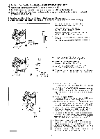
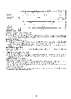
Stitch length Stichlange Needle height Nadelhohe LT2-B841 -3 -5 2 mm 3 mm [H] [H] LT2-B842 -3 -5 2 mm 2.4 mm LT2-B845 LT2-B847 LT2-B848 -3 -5 -7 -1 -1 3 mm 2 mm 2.0 mm Stitch length Stichlange Needle height Nadelhohe LT2-6872 -3 -5 [H] [H] LT2-B875 -3 -5 -7 3 mm 2.4 mm Needle bar height (LT2-B841, B842, B847, B872) (1) Set the feed adjustment dial to the "0" position. 0. (2) When the needle bar 0 is in its lowest position, the needle position reference line 0 of the needle bar must be aligned with the bottom edge of the needle bar support Loosen the set screw 0, and align the needle position reference line ® of the needle bar with the bottom edge of the needle bar support 0. Needle bar lift stroke (1) Turn the feed-adjustment dial to 2 or 3. (2) When the needle bar 0 is H mm (2.4 mm or 2.0 mm) above its lowest position, needle position reference line "b" of the needle bar is aligned with the bottom edge of the needle bar. At this time, the rotary hook point must be aligned with the needle center. Loosen the three set screws 0, and align the rotary hook point with the needle center. (3) When the rotary hook point is aligned with the needle center, confirm that the space between the top of the needle eye and rotary hook point is 1 - 1.5 mm. (Model LT2-B845, B848, B875) al) Remove the set screw turn the needle clamp screw 0, and adjust so that the space between the rotary hook point and the top of the needle eye is 1 - 1.5 mm. Nadelhohe (LT2-B841, B842, B847, B872) (1) Die Transporteinstellscheibe auf "0" stellen. (2) Wenn die Nadelstange 0 in der untersten Position steht, mug die Bezugslinie ® mit der Unterkante der Nadelstangenbuchse ausgerichtet sein. Lasen Sie die Schraube 0, um die Bezugslinie ® der Nadelstange mit der Unterkante der Nadelstangenbuchse 0 auszurichten. Einstellung des Nadelstangenhubs (1) Die Transporteinstellscheibe auf "2 oder 3" stellen. (2) Wenn die Nadelstange 0 H mm (2,4 mm oder 2,0 mm) tither der untersten Position steht, mug die Bezugslinie "b" mit der Unterkante der Nadelstangebuchse ausgerichtet sein. Der Greifer mug auf die Nadelmitte ausgerichtet sein. Der Greifer kann auf die Nadelmitte eingstellt werden, wenn die drei Schrauben 0 gelost werden. (3) Wenn der Greifer auf die Nadelmitte ausgerichtet ist, kontrollieren, ob der Abstand zwischen der oberen Seite des Nadelohrs und dem Greifer 1 - 1,5 mm betragt. (Modell LT2-B845, B848, B875) Der Abstand zwischen der oberen Seite des Nadelohrs und dem Greifer kann eingestellt werden, wenn die Schraube entfernt und die Einstellschraube 0 am Nadelhalter gedreht wird.
-
 1
1 -
2
-
3
-
4
-
5
-
6
-
7
-
8
-
9
-
10
-
11
-
12
-
13
-
14
-
15
-
16
-
17
-
18
-
19
-
20
-
21
-
22
-
23
-
24
-
25
-
26
-
27
-
 28
28 -
 29
29 -
 30
30 -
 31
31 -
 32
32 -
 33
33 -
 34
34 -
 35
35 -
 36
36 -
 37
37 -
 38
38 -
39
-
40
-
41
-
42
-
43
-
44
-
45
-
46
 |
 |
