Cisco WS-C3560E-48PD-SF Hardware Installation Guide - Page 102
Preparing for Installation, Grounding the Switch
 |
View all Cisco WS-C3560E-48PD-SF manuals
Add to My Manuals
Save this manual to your list of manuals |
Page 102 highlights
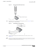
Connecting to DC Power Appendix C Connecting to DC Power Caution The Catalyst 3560V2-24TS-SD switch is suitable only for intrabuilding or nonexposed wiring connections. Preparing for Installation Locate the ground lug and the two number-10-32 screws on the switch rear panel and the DC terminal block plug in the DC-switch accessory kit. Obtain these necessary tools and equipment: • Ratcheting torque screwdriver with a Phillips head that exerts up to 15 pound-force inches (lbf-in.) or 240 ounce-force inches (ozf-in.) of pressure • Panduit crimping tool with optional controlled cycle mechanism (model CT-700, CT-720, CT-920, CT-920CH, CT-930, or CT-940CH) • 6-gauge copper ground wire (insulated or noninsulated) • Four leads of 18-gauge copper wire • Wire-stripping tools for stripping 6- and 18-gauge wires Grounding the Switch Warning This equipment must be grounded. Never defeat the ground conductor or operate the equipment in the absence of a suitably installed ground conductor. Contact the appropriate electrical inspection authority or an electrician if you are uncertain that suitable grounding is available. Statement 1024 Caution To make sure that the equipment is reliably connected to earth ground, follow the grounding procedure instructions, and use a UL-listed lug suitable for number-6 AWG wire and two number-10-32 ground-lug screws. To ground the switch to earth ground, follow these steps. Make sure to follow any grounding requirements at your site. Step 1 Step 2 Locate and remove the ground lug and the two number-10-32 ground-lug screws from the rear panel of the switch. (See Figure C-3 for location.) Use a standard Phillips screwdriver or a ratcheting torque screwdriver with a Phillips head. Set the screws and the ground lug aside. If your ground wire is insulated, use a wire stripping tool to strip the 6-gauge ground wire to 0.5 inch (12.7 mm) ± 0.02 inch (0.5 mm), as shown in Figure C-1. Catalyst 3560 Switch Hardware Installation Guide C-2 OL-6337-07
-
 1
1 -
2
-
3
-
4
-
5
-
6
-
7
-
8
-
9
-
10
-
11
-
12
-
13
-
14
-
15
-
16
-
17
-
18
-
19
-
20
-
21
-
22
-
23
-
24
-
25
-
26
-
27
-
28
-
29
-
30
-
31
-
32
-
33
-
34
-
35
-
36
-
37
-
38
-
39
-
40
-
41
-
42
-
43
-
44
-
45
-
46
-
47
-
48
-
49
-
50
-
51
-
52
-
53
-
54
-
55
-
56
-
57
-
58
-
59
-
60
-
61
-
62
-
63
-
64
-
65
-
66
-
67
-
68
-
69
-
70
-
71
-
72
-
73
-
74
-
75
-
76
-
77
-
78
-
79
-
80
-
81
-
82
-
83
-
84
-
85
-
86
-
87
-
88
-
89
-
90
-
91
-
92
-
93
-
94
-
95
-
96
-
 97
97 -
 98
98 -
 99
99 -
 100
100 -
 101
101 -
 102
102 -
 103
103 -
 104
104 -
 105
105 -
 106
106 -
 107
107 -
108
-
109
-
110
-
111
-
112
-
113
-
114
-
115
-
116
-
117
-
118
-
119
-
120
 |
 |
