Cisco WS-C3560E-48PD-SF Hardware Installation Guide - Page 69
Installing the Mounting Screws on a Wall, Step 3
 |
View all Cisco WS-C3560E-48PD-SF manuals
Add to My Manuals
Save this manual to your list of manuals |
Page 69 highlights
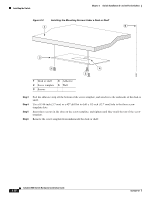
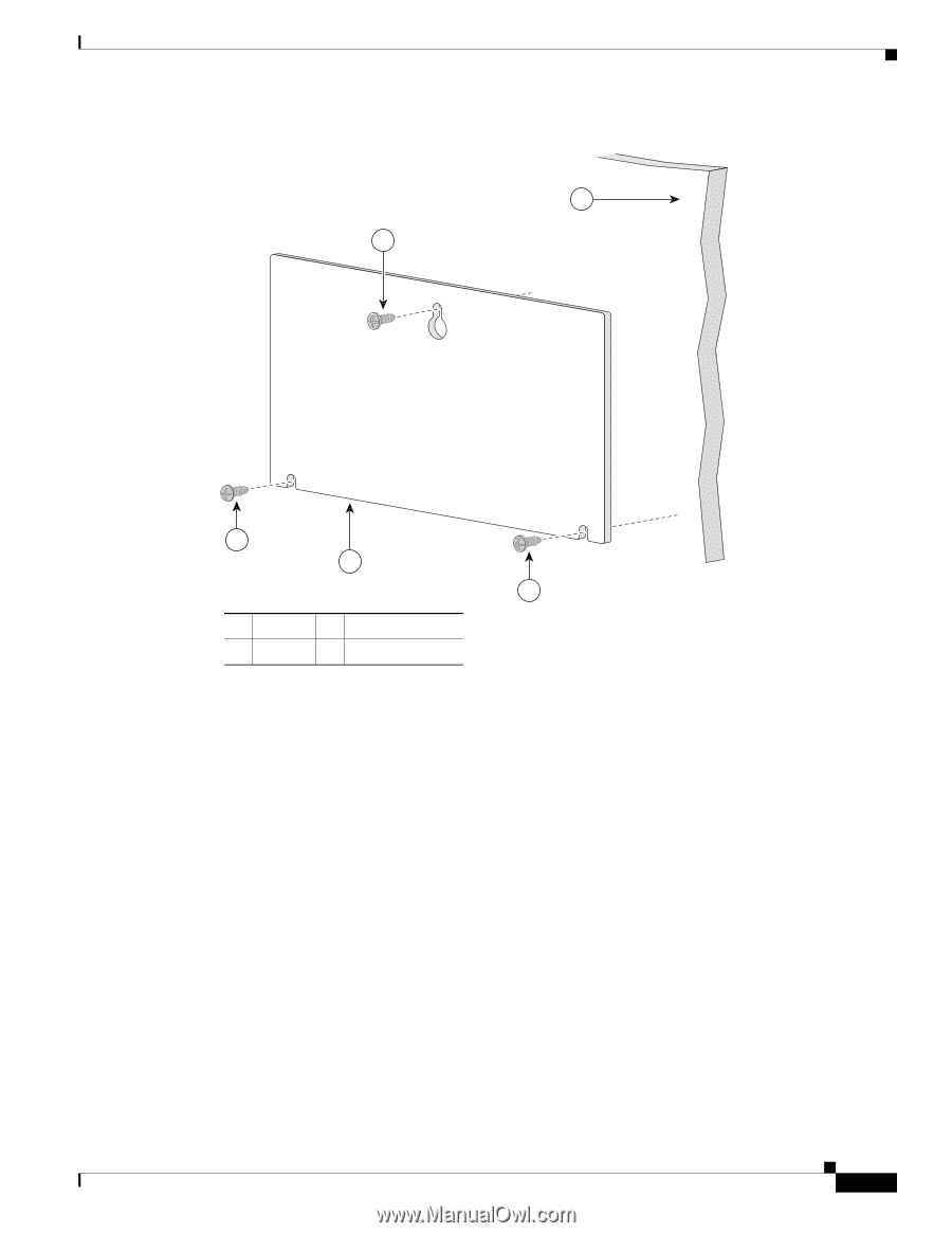
Chapter 3 Switch Installation (8- and 12-Port Switches) Figure 3-5 Installing the Mounting Screws on a Wall 1 2 Installing the Switch TMHIOSUSNIDTIENAGWSAUYRFFRAOCEM 157828 CABLE SIDE ENTRY 2 3 2 1 Wall 3 Screw template 2 Screws Step 3 Step 4 Step 5 Step 6 Step 7 Peel the adhesive strip off the bottom of the screw template. Attach the screw template to the wall. Use a 0.144-inch (3.7 mm) or a #27 drill bit to drill a 1/2 inch (12.7 mm) hole in the three screw template slots. Insert three screws in the slots on the screw template, and tighten until they touch the top of the screw template. Remove the screw template from the wall. OL-6337-07 Catalyst 3560 Switch Hardware Installation Guide 3-13
-
 1
1 -
2
-
3
-
4
-
5
-
6
-
7
-
8
-
9
-
10
-
11
-
12
-
13
-
14
-
15
-
16
-
17
-
18
-
19
-
20
-
21
-
22
-
23
-
24
-
25
-
26
-
27
-
28
-
29
-
30
-
31
-
32
-
33
-
34
-
35
-
36
-
37
-
38
-
39
-
40
-
41
-
42
-
43
-
44
-
45
-
46
-
47
-
48
-
49
-
50
-
51
-
52
-
53
-
54
-
55
-
56
-
57
-
58
-
59
-
60
-
61
-
62
-
63
-
 64
64 -
 65
65 -
 66
66 -
 67
67 -
 68
68 -
 69
69 -
 70
70 -
 71
71 -
 72
72 -
 73
73 -
 74
74 -
75
-
76
-
77
-
78
-
79
-
80
-
81
-
82
-
83
-
84
-
85
-
86
-
87
-
88
-
89
-
90
-
91
-
92
-
93
-
94
-
95
-
96
-
97
-
98
-
99
-
100
-
101
-
102
-
103
-
104
-
105
-
106
-
107
-
108
-
109
-
110
-
111
-
112
-
113
-
114
-
115
-
116
-
117
-
118
-
119
-
120
 |
 |
3-13
Catalyst 3560 Switch Hardware Installation Guide
OL-6337-07
Chapter 3
Switch Installation (8- and 12-Port Switches)
Installing the Switch
Figure 3-5
Installing the Mounting Screws on a Wall
Step 3
Peel the adhesive strip off the bottom of the screw template.
Step 4
Attach the screw template to the wall.
Step 5
Use a 0.144-inch (3.7 mm) or a #27 drill bit to drill a 1/2 inch (12.7 mm) hole in the three screw
template slots.
Step 6
Insert three screws in the slots on the screw template, and tighten until they touch the top of the
screw template.
Step 7
Remove the screw template from the wall.
1
Wall
3
Screw template
2
Screws
CABLE SIDE ENTRY
THIS SIDE AWAY FROM
MOUNTING SURFACE
2
3
2
2
1
157828