Cisco WS-C3560E-48PD-SF Hardware Installation Guide - Page 55
Connecting to a Dual-Purpose Port
 |
View all Cisco WS-C3560E-48PD-SF manuals
Add to My Manuals
Save this manual to your list of manuals |
Page 55 highlights
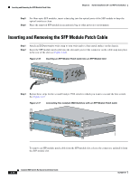
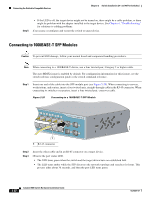
Chapter 2 Switch Installation (24- and 48-Port Switches) Connecting the Switch to Compatible Devices Step 4 • If the LED is off, the target device might not be turned on, there might be a cable problem, or there might be problem with the adapter installed in the target device. See Chapter 4, "Troubleshooting," for solutions to cabling problems. If necessary, reconfigure and restart the switch or target device. Connecting to a Dual-Purpose Port Step 1 Connect an RJ-45 connector to the 10/100/1000 port, or install an SFP module into the SFP module slot, and connect a cable to the SFP module port, as shown in Figure 2-21. Figure 2-21 Connecting to a Dual-Purpose Port 5x 6x 7x 8x 1 2 Catalyst 3560 SERIES PoE-8 1 210093 1 RJ-45 connector 2 LC connector Step 2 Only one port can be active at a time. If both ports are connected, the SFP module port has priority. You cannot configure the priority setting. Connect the other end of the cable to the other device. The switch automatically detects the connection and configures the port. Note By default, the switch detects whether an RJ-45 connector or SFP module is connected to a dual-purpose port and configures the port accordingly. You can change this setting and configure the port to recognize only an RJ-45 connector or only an SFP module by using the media type interface configuration command. For more information, see the command reference. OL-6337-07 Catalyst 3560 Switch Hardware Installation Guide 2-23
-
 1
1 -
2
-
3
-
4
-
5
-
6
-
7
-
8
-
9
-
10
-
11
-
12
-
13
-
14
-
15
-
16
-
17
-
18
-
19
-
20
-
21
-
22
-
23
-
24
-
25
-
26
-
27
-
28
-
29
-
30
-
31
-
32
-
33
-
34
-
35
-
36
-
37
-
38
-
39
-
40
-
41
-
42
-
43
-
44
-
45
-
46
-
47
-
48
-
49
-
 50
50 -
 51
51 -
 52
52 -
 53
53 -
 54
54 -
 55
55 -
 56
56 -
 57
57 -
 58
58 -
 59
59 -
 60
60 -
61
-
62
-
63
-
64
-
65
-
66
-
67
-
68
-
69
-
70
-
71
-
72
-
73
-
74
-
75
-
76
-
77
-
78
-
79
-
80
-
81
-
82
-
83
-
84
-
85
-
86
-
87
-
88
-
89
-
90
-
91
-
92
-
93
-
94
-
95
-
96
-
97
-
98
-
99
-
100
-
101
-
102
-
103
-
104
-
105
-
106
-
107
-
108
-
109
-
110
-
111
-
112
-
113
-
114
-
115
-
116
-
117
-
118
-
119
-
120
 |
 |
