Cisco WS-C3560E-48PD-SF Hardware Installation Guide - Page 64
Desk or Shelf Mounting, Desk or Shelf Mounting (Unsecured)
 |
View all Cisco WS-C3560E-48PD-SF manuals
Add to My Manuals
Save this manual to your list of manuals |
Page 64 highlights
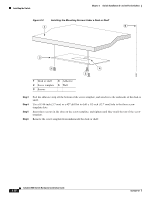
Installing the Switch Chapter 3 Switch Installation (8- and 12-Port Switches) Desk or Shelf Mounting • Desk or Shelf Mounting (Unsecured), page 3-8 • Desk or Shelf Mounting (Secured), page 3-8 • Under the Desk or Shelf Mounting, page 3-9 Desk or Shelf Mounting (Unsecured) Step 1 Step 2 Locate the adhesive strip with the rubber feet in the accessory kit. Remove the four rubber feet from the adhesive strip, and attach them to the recessed areas on the bottom of the unit. They prevent the switch from sliding on the desk or shelf. Step 3 Note We strongly recommend that you attach the rubber feet. Doing so improves airflow and reduces overheating. Place the switch on the desk or shelf. Desk or Shelf Mounting (Secured) Step 1 Step 2 Locate the screw template. The template is used to align the mounting screw holes and is also a guide for making sure that the screws have proper clearance. Position the screw template on top of the desk or shelf so that the two side-by-side slots face the front of the desk or shelf, as shown in Figure 3-1. This ensures that the power cord faces the rear of the desk or shelf after the switch is installed. Note Wait before you attach the screw template to the desk or shelf. Figure 3-1 3 Installing the Mounting Screws on a Desk or Shelf 2 1 210096 1 Screw template 3 Desk or shelf 2 Screws Step 3 Peel the adhesive strip off the bottom of the screw template, and attach it to the top of the desk or shelf. Catalyst 3560 Switch Hardware Installation Guide 3-8 OL-6337-07
-
 1
1 -
2
-
3
-
4
-
5
-
6
-
7
-
8
-
9
-
10
-
11
-
12
-
13
-
14
-
15
-
16
-
17
-
18
-
19
-
20
-
21
-
22
-
23
-
24
-
25
-
26
-
27
-
28
-
29
-
30
-
31
-
32
-
33
-
34
-
35
-
36
-
37
-
38
-
39
-
40
-
41
-
42
-
43
-
44
-
45
-
46
-
47
-
48
-
49
-
50
-
51
-
52
-
53
-
54
-
55
-
56
-
57
-
58
-
 59
59 -
 60
60 -
 61
61 -
 62
62 -
 63
63 -
 64
64 -
 65
65 -
 66
66 -
 67
67 -
 68
68 -
 69
69 -
70
-
71
-
72
-
73
-
74
-
75
-
76
-
77
-
78
-
79
-
80
-
81
-
82
-
83
-
84
-
85
-
86
-
87
-
88
-
89
-
90
-
91
-
92
-
93
-
94
-
95
-
96
-
97
-
98
-
99
-
100
-
101
-
102
-
103
-
104
-
105
-
106
-
107
-
108
-
109
-
110
-
111
-
112
-
113
-
114
-
115
-
116
-
117
-
118
-
119
-
120
 |
 |
