Cisco WS-C3560E-48PD-SF Hardware Installation Guide - Page 29
Cisco RPS, Cisco RPS 2300, Console Port
 |
View all Cisco WS-C3560E-48PD-SF manuals
Add to My Manuals
Save this manual to your list of manuals |
Page 29 highlights
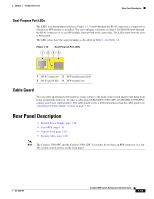
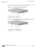
Chapter 1 Product Overview Rear Panel Description Cisco RPS Depending on the switch model, you can connect the switch to either of these Cisco redundant power systems (RPS) to provide backup power if the switch power supply fails: • "Cisco RPS 2300" section on page 1-19 • "Cisco RPS 675" section on page 1-19 Connect the switch and the Cisco RPS to the same AC power source. Use the RPS connector cable supplied with the RPS to connect the RPS to the switch. Note When an RPS is connected to the Catalyst 3560V2-24TS-SD switch, the switch is not Network Equipment Building Systems (NEBS) compliant. Note The Catalyst 3560-8PC and Catalyst 3560-12PC-S switches do not have an RPS connector. For complete information about the Cisco RPS products, including compatibility matrixes listing the supported RPS for each Catalyst 3560 switch, see the RPS documents on Cisco.com: http://www.cisco.com/en/US/products/ps7148/prod_installation_guides_list.html Cisco RPS 2300 The Cisco RPS 2300 is a redundant power system that supports six network switches and provides power to one or two failed switches at a time. It automatically senses when the internal power supply of a connected switch fails and provides power to the failed switch, preventing loss of network traffic. The Cisco RPS 2300 has two output levels: -52 V and 12 V. The maximum output power depends on the installed power-supply modules. Cisco RPS 675 The Cisco 675 RPS is a redundant power system that supports six network devices and provides power to one failed switch at a time. It automatically senses when the internal power supply of a connected switch fails and provides power to the failed switch, preventing loss of network traffic. The Cisco RPS 675 has two output levels: -48 V and 12 V. The maximum output power is 675 W. Console Port You can connect the switch to a PC by means of the console port and the supplied RJ-45-to-DB-9 female cable. If you want to connect the switch console port to a terminal, you need to provide an RJ-45-to-DB-25 female DTE adapter. You can order a kit (part number ACS-DSBUASYN=) containing that adapter from Cisco. For console port and adapter pinout information, see the "Connector and Cable Specifications" section on page B-1. OL-6337-07 Catalyst 3560 Switch Hardware Installation Guide 1-19
-
 1
1 -
2
-
3
-
4
-
5
-
6
-
7
-
8
-
9
-
10
-
11
-
12
-
13
-
14
-
15
-
16
-
17
-
18
-
19
-
20
-
21
-
22
-
23
-
 24
24 -
 25
25 -
 26
26 -
 27
27 -
 28
28 -
 29
29 -
 30
30 -
 31
31 -
 32
32 -
 33
33 -
 34
34 -
35
-
36
-
37
-
38
-
39
-
40
-
41
-
42
-
43
-
44
-
45
-
46
-
47
-
48
-
49
-
50
-
51
-
52
-
53
-
54
-
55
-
56
-
57
-
58
-
59
-
60
-
61
-
62
-
63
-
64
-
65
-
66
-
67
-
68
-
69
-
70
-
71
-
72
-
73
-
74
-
75
-
76
-
77
-
78
-
79
-
80
-
81
-
82
-
83
-
84
-
85
-
86
-
87
-
88
-
89
-
90
-
91
-
92
-
93
-
94
-
95
-
96
-
97
-
98
-
99
-
100
-
101
-
102
-
103
-
104
-
105
-
106
-
107
-
108
-
109
-
110
-
111
-
112
-
113
-
114
-
115
-
116
-
117
-
118
-
119
-
120
 |
 |