Cisco WS-C3560E-48PD-SF Hardware Installation Guide - Page 20
SFP Module Slots, SFP Modules, SFP Module Patch Cable, Dual-Purpose Port - replacement
 |
View all Cisco WS-C3560E-48PD-SF manuals
Add to My Manuals
Save this manual to your list of manuals |
Page 20 highlights
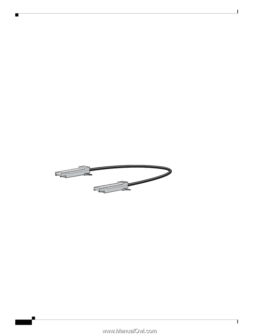
Front Panel Description Chapter 1 Product Overview Many legacy powered devices, including older Cisco IP phones and access points that do not fully support IEEE 802.3af, might not support PoE when connected to the switches by a crossover cable. SFP Module Slots See the release notes for the latest list of supported SFP modules. SFP Modules The switch uses Gigabit Ethernet SFP modules to establish fiber-optic and 1000BASE-T connections. These transceiver modules are field-replaceable, providing uplink interfaces when inserted in an SFP module slot. Use fiber-optic cables with LC or MT-RJ connectors to connect to a fiber-optic SFP module. Use a Category 5 cable with RJ-45 connectors to connect to a copper SFP module. For more information about SFP modules, see your SFP module documentation or the release note for your switch software. SFP Module Patch Cable The switch supports the SFP module patch cable (CAB-SFP-50CM=), a 0.5 meter, copper, passive cable with SFP module connectors at each end (see Figure 1-11). Figure 1-11 SFP Module Patch Cable 126809 The SFP module patch cable can connect only two Catalyst 3560 switches. To connect a Catalyst 3560 switch to other Catalyst series switches, you must use the SFP modules specified in the "SFP Module Cable Specifications" section on page B-4. See "Inserting and Removing the SFP Module Patch Cable" section on page 2-18 for more information about using the SFP module patch cable. Dual-Purpose Port You can configure a dual-purpose port as either a 10/100/1000 port or as an SFP module port. Each port is considered as a single interface with dual front ends-an RJ-45 connector and an SFP module connector. The dual front ends are not redundant interfaces. The switch activates only one connector of the pair at a time. By default, the switch dynamically selects the interface type that first links up. However, you can use the media-type interface configuration command to select the RJ-45 connector or the SFP module connector. For information about configuring speed and duplex settings for a dual-purpose uplink, see the software configuration guide. Each uplink port has two LEDs. One shows the status of the RJ-45 port, and one shows the status of the SFP module port. The port LED is on for the active connector. 1-10 Catalyst 3560 Switch Hardware Installation Guide OL-6337-07
-
 1
1 -
2
-
3
-
4
-
5
-
6
-
7
-
8
-
9
-
10
-
11
-
12
-
13
-
14
-
 15
15 -
 16
16 -
 17
17 -
 18
18 -
 19
19 -
 20
20 -
 21
21 -
 22
22 -
 23
23 -
 24
24 -
 25
25 -
26
-
27
-
28
-
29
-
30
-
31
-
32
-
33
-
34
-
35
-
36
-
37
-
38
-
39
-
40
-
41
-
42
-
43
-
44
-
45
-
46
-
47
-
48
-
49
-
50
-
51
-
52
-
53
-
54
-
55
-
56
-
57
-
58
-
59
-
60
-
61
-
62
-
63
-
64
-
65
-
66
-
67
-
68
-
69
-
70
-
71
-
72
-
73
-
74
-
75
-
76
-
77
-
78
-
79
-
80
-
81
-
82
-
83
-
84
-
85
-
86
-
87
-
88
-
89
-
90
-
91
-
92
-
93
-
94
-
95
-
96
-
97
-
98
-
99
-
100
-
101
-
102
-
103
-
104
-
105
-
106
-
107
-
108
-
109
-
110
-
111
-
112
-
113
-
114
-
115
-
116
-
117
-
118
-
119
-
120
 |
 |