Cisco WS-C3560E-48PD-SF Hardware Installation Guide - Page 97
Two Twisted-Pair Cable Pinouts, SFP Module, Wavelength, nanometers, Fiber Type, Core Size/Cladding
 |
View all Cisco WS-C3560E-48PD-SF manuals
Add to My Manuals
Save this manual to your list of manuals |
Page 97 highlights
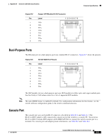
Appendix B Connector and Cable Specifications Cable and Adapter Specifications Table B-1 Fiber-Optic SFP Module Port Cabling Specifications (continued) SFP Module CWDM Wavelength (nanometers) 1470, 1490, 1510, 1530, 1550, 1570, 1590, 1610 Fiber Type SMF Core Size/Cladding Modal Bandwidth Size (micron) (MHz/km)1 Cable Distance G.6522 - 62 miles (100 km) DWDM ITU channels - - 21-59 - - 1. Modal bandwidth applies only to multimode fiber. 2. A mode-field diameter/cladding diameter = 9 micrometers/125 micrometers 3. A mode-conditioning patch cord is required. Using an ordinary patch cord with MMF, 1000BASE-LX/LH SFP modules, and a short link distance can cause transceiver saturation, resulting in an elevated bit error rate (BER). When using the LX/LH SFP module with 62.5-micron diameter MMF, you must also install a mode-conditioning patch cord between the SFP module and the MMF cable on both the sending and receiving ends of the link. The mode-conditioning patch cord is required for link distances greater than 984 feet (300 m). 4. 1000BASE-ZX SFP modules can send data up to 62 miles (100 km) by using dispersion-shifted SMF or low-attenuation SMF; the distance depends on the fiber quality, the number of splices, and the connectors. Two Twisted-Pair Cable Pinouts Figure B-6 and Figure B-7 show the schematics of two twisted-pair cables for connecting to 10BASE-Tand 100BASE-TX-compatible devices. Figure B-6 Switch 3 TD+ 6 TD- 1 RD+ 2 RD- Two Twisted-Pair Straight-Through Cable Schematic Router or PC 3 RD+ 6 RD- 1 TD+ 2 TD- H5578 Figure B-7 Switch 3 TD+ 6 TD- 1 RD+ 2 RD- Two Twisted-Pair Crossover Cable Schematic Switch 3 TD+ 6 TD- 1 RD+ 2 RD- H5579 OL-6337-07 Catalyst 3560 Switch Hardware Installation Guide B-5
-
 1
1 -
2
-
3
-
4
-
5
-
6
-
7
-
8
-
9
-
10
-
11
-
12
-
13
-
14
-
15
-
16
-
17
-
18
-
19
-
20
-
21
-
22
-
23
-
24
-
25
-
26
-
27
-
28
-
29
-
30
-
31
-
32
-
33
-
34
-
35
-
36
-
37
-
38
-
39
-
40
-
41
-
42
-
43
-
44
-
45
-
46
-
47
-
48
-
49
-
50
-
51
-
52
-
53
-
54
-
55
-
56
-
57
-
58
-
59
-
60
-
61
-
62
-
63
-
64
-
65
-
66
-
67
-
68
-
69
-
70
-
71
-
72
-
73
-
74
-
75
-
76
-
77
-
78
-
79
-
80
-
81
-
82
-
83
-
84
-
85
-
86
-
87
-
88
-
89
-
90
-
91
-
 92
92 -
 93
93 -
 94
94 -
 95
95 -
 96
96 -
 97
97 -
 98
98 -
 99
99 -
 100
100 -
 101
101 -
 102
102 -
103
-
104
-
105
-
106
-
107
-
108
-
109
-
110
-
111
-
112
-
113
-
114
-
115
-
116
-
117
-
118
-
119
-
120
 |
 |
