Cisco WS-C3560E-48PD-SF Hardware Installation Guide - Page 98
Four Twisted-Pair Cable Pinouts for 1000BASE-T Ports, Identifying a Crossover Cable
 |
View all Cisco WS-C3560E-48PD-SF manuals
Add to My Manuals
Save this manual to your list of manuals |
Page 98 highlights
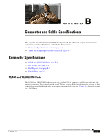
Cable and Adapter Specifications Appendix B Connector and Cable Specifications Four Twisted-Pair Cable Pinouts for 1000BASE-T Ports Figure B-8 and Figure B-9 show the schematics of four twisted-pair cables for 1000BASE-T SFP module ports on Catalyst 3560 switches. Figure B-8 Switch 1 TP0+ 2 TP03 TP1+ 6 TP1- Four Twisted-Pair Straight-Through Cable Schematic for 1000BASE-T Ports Router or PC 1 TP0+ 2 TP03 TP1+ 6 TP1- 4 TP2+ 5 TP27 TP3+ 8 TP3- Figure B-9 65271 4 TP2+ 5 TP27 TP3+ 8 TP3- Four Twisted-Pair Crossover Cable Schematics for 1000BASE-T Ports Identifying a Crossover Cable To identify a crossover cable, compare the two modular ends of the cable. Hold the cable ends side-by-side, with the tab at the back. The wire connected to the pin on the outside of the left plug should be a different color from the wire connected to the pin on the inside of the right plug. (See Figure B-10.) Catalyst 3560 Switch Hardware Installation Guide B-6 OL-6337-07
-
 1
1 -
2
-
3
-
4
-
5
-
6
-
7
-
8
-
9
-
10
-
11
-
12
-
13
-
14
-
15
-
16
-
17
-
18
-
19
-
20
-
21
-
22
-
23
-
24
-
25
-
26
-
27
-
28
-
29
-
30
-
31
-
32
-
33
-
34
-
35
-
36
-
37
-
38
-
39
-
40
-
41
-
42
-
43
-
44
-
45
-
46
-
47
-
48
-
49
-
50
-
51
-
52
-
53
-
54
-
55
-
56
-
57
-
58
-
59
-
60
-
61
-
62
-
63
-
64
-
65
-
66
-
67
-
68
-
69
-
70
-
71
-
72
-
73
-
74
-
75
-
76
-
77
-
78
-
79
-
80
-
81
-
82
-
83
-
84
-
85
-
86
-
87
-
88
-
89
-
90
-
91
-
92
-
 93
93 -
 94
94 -
 95
95 -
 96
96 -
 97
97 -
 98
98 -
 99
99 -
 100
100 -
 101
101 -
 102
102 -
 103
103 -
104
-
105
-
106
-
107
-
108
-
109
-
110
-
111
-
112
-
113
-
114
-
115
-
116
-
117
-
118
-
119
-
120
 |
 |