Cisco WS-C3560E-48PD-SF Hardware Installation Guide - Page 17
Catalyst 3560G-24TS Switch Front Panel, Catalyst 3560G-48PS Switch Front
 |
View all Cisco WS-C3560E-48PD-SF manuals
Add to My Manuals
Save this manual to your list of manuals |
Page 17 highlights
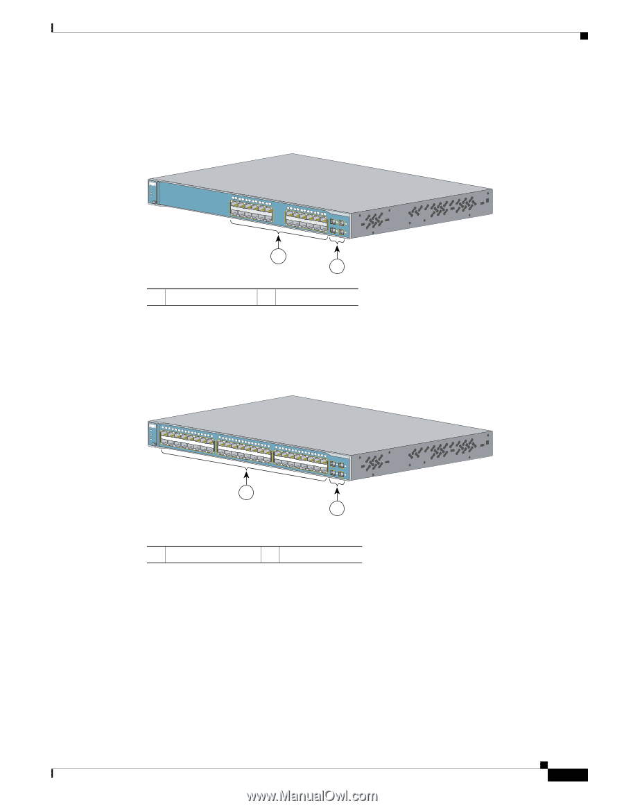
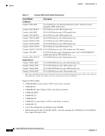
Chapter 1 Product Overview Front Panel Description The 10/100/1000 ports on the Catalyst 3560-24TS switch are grouped in pairs. The first member of the pair (port 1) is above the second member (port 2) on the left, as shown in Figure 1-8. Port 3 is above port 4, and so on. The SFP module slots are numbered 25 to 28. Figure 1-8 Catalyst 3560G-24TS Switch Front Panel 119677 SYST RPS STAT DUPLX SPEED MODE 12 1X 34 56 78 9 10 11 12 11X 2X 12X 13 14 13X 15 16 17 18 19 20 21 22 23 24 23X Catalyst 3560G SERIES 25 14X 27 24X 26 28 1 2 1 10/100/1000 ports 2 SFP module slots The 10/100/1000 PoE ports on the Catalyst 3560G-48PS switch are grouped in pairs. The first member of the pair (port 1) is above the second member (port 2) on the left, as shown in Figure 1-9. Port 3 is above port 4, and so on. The SFP module slots are numbered 49 to 52. Figure 1-9 Catalyst 3560G-48PS Switch Front Panel 119674 SYST RPS STAT DUPLX SPEED PoE MODE 1 1X 2X 23 45 67 8 9 10 11 12 13 14 15 16 17 15X 17X 18 19 20 21 22 23 24 25 26 27 28 29 30 31 32 16X 18X 33 31X 33X 34 35 36 37 38 39 40 41 42 43 44 45 46 47 48 Catalyst 3560G SERIES PoE-48 47X 32X 34X 49 51 48X 50 52 1 2 1 10/100/1000 ports 2 SFP module slots OL-6337-07 Catalyst 3560 Switch Hardware Installation Guide 1-7
-
 1
1 -
2
-
3
-
4
-
5
-
6
-
7
-
8
-
9
-
10
-
11
-
 12
12 -
 13
13 -
 14
14 -
 15
15 -
 16
16 -
 17
17 -
 18
18 -
 19
19 -
 20
20 -
 21
21 -
 22
22 -
23
-
24
-
25
-
26
-
27
-
28
-
29
-
30
-
31
-
32
-
33
-
34
-
35
-
36
-
37
-
38
-
39
-
40
-
41
-
42
-
43
-
44
-
45
-
46
-
47
-
48
-
49
-
50
-
51
-
52
-
53
-
54
-
55
-
56
-
57
-
58
-
59
-
60
-
61
-
62
-
63
-
64
-
65
-
66
-
67
-
68
-
69
-
70
-
71
-
72
-
73
-
74
-
75
-
76
-
77
-
78
-
79
-
80
-
81
-
82
-
83
-
84
-
85
-
86
-
87
-
88
-
89
-
90
-
91
-
92
-
93
-
94
-
95
-
96
-
97
-
98
-
99
-
100
-
101
-
102
-
103
-
104
-
105
-
106
-
107
-
108
-
109
-
110
-
111
-
112
-
113
-
114
-
115
-
116
-
117
-
118
-
119
-
120
 |
 |