Cisco WS-C3560E-48PD-SF Hardware Installation Guide - Page 107
C-8, Torquing the Terminal-Block Captive Screws, Completed Wiring of Terminal Block Plug
 |
View all Cisco WS-C3560E-48PD-SF manuals
Add to My Manuals
Save this manual to your list of manuals |
Page 107 highlights
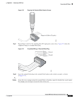
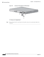
Appendix C Connecting to DC Power Figure C-8 Torquing the Terminal-Block Captive Screws Connecting to DC Power Torque to 4.5 lbf-in. (72 ozf-in.) 60533 Step 7 Repeat Steps 4 and 5 for the remaining three DC-input power source wires. Figure C-9 shows the completed wiring of a terminal block plug. Figure C-9 Completed Wiring of Terminal Block Plug Return Negative Return Negative Feed A Feed B 60534 Step 8 Insert the terminal block plug in the terminal block header on the switch rear panel, as shown in Figure C-10. Caution Secure the wires coming in from the terminal block so that they cannot be disturbed by casual contact. For example, use tie wraps to secure the wires to the rack. OL-6337-07 Catalyst 3560 Switch Hardware Installation Guide C-7
-
 1
1 -
2
-
3
-
4
-
5
-
6
-
7
-
8
-
9
-
10
-
11
-
12
-
13
-
14
-
15
-
16
-
17
-
18
-
19
-
20
-
21
-
22
-
23
-
24
-
25
-
26
-
27
-
28
-
29
-
30
-
31
-
32
-
33
-
34
-
35
-
36
-
37
-
38
-
39
-
40
-
41
-
42
-
43
-
44
-
45
-
46
-
47
-
48
-
49
-
50
-
51
-
52
-
53
-
54
-
55
-
56
-
57
-
58
-
59
-
60
-
61
-
62
-
63
-
64
-
65
-
66
-
67
-
68
-
69
-
70
-
71
-
72
-
73
-
74
-
75
-
76
-
77
-
78
-
79
-
80
-
81
-
82
-
83
-
84
-
85
-
86
-
87
-
88
-
89
-
90
-
91
-
92
-
93
-
94
-
95
-
96
-
97
-
98
-
99
-
100
-
101
-
 102
102 -
 103
103 -
 104
104 -
 105
105 -
 106
106 -
 107
107 -
 108
108 -
 109
109 -
 110
110 -
 111
111 -
 112
112 -
113
-
114
-
115
-
116
-
117
-
118
-
119
-
120
 |
 |
