Cisco WS-C3560E-48PD-SF Hardware Installation Guide - Page 47
Table- or Shelf- Mounting, Installing and Removing SFP Modules
 |
View all Cisco WS-C3560E-48PD-SF manuals
Add to My Manuals
Save this manual to your list of manuals |
Page 47 highlights
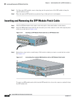
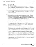
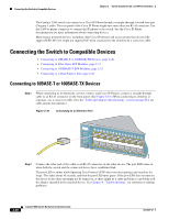
Chapter 2 Switch Installation (24- and 48-Port Switches) Installing and Removing SFP Modules Table- or Shelf- Mounting Step 1 Locate the adhesive strip with the rubber feet in the mounting-kit envelope. Attach the four rubber feet to the bottom of the switch near the corners. Note Do not attach the rubber feet over the recessed screw holes on the bottom of the switch. Step 2 Place the switch on the table or shelf near an AC power source. After the switch is mounted in the rack: 1. Power on the switch. See the "Verifying Switch Operation" section on page 2-6. 2. Connect to a 10/100 or 10/100/1000 port, and run Express Setup. See the Catalyst 3560 Switch Getting Started Guide for instructions. To use the CLI setup program, see Appendix D, "Configuring the Switch with the CLI-Based Setup Program." 3. Connect to the front-panel ports. Note When the connectors are not being used, replace the dust covers on them for protection. Installing and Removing SFP Modules The SFP modules are inserted into the SFP module slots on the front and provide uplink interfaces. You can use any combination of SFP modules. See the Catalyst 3560 release notes for the list of supported SFP modules. Each port must match the wave-length specifications on the other end of the cable, and for reliable communications, the cable must not exceed the stipulated cable length. See the Table B-1 on page B-4 for cable stipulations for SFP connections. Use only Cisco SFP modules. Each SFP module has an internal serial EEPROM that is encoded with security information, which Cisco uses to identify and validate that the SFP module meets the requirements for the switch. For detailed instructions on installing, removing, and cabling the SFP module, see the SFP module documentation. OL-6337-07 Catalyst 3560 Switch Hardware Installation Guide 2-15
-
 1
1 -
2
-
3
-
4
-
5
-
6
-
7
-
8
-
9
-
10
-
11
-
12
-
13
-
14
-
15
-
16
-
17
-
18
-
19
-
20
-
21
-
22
-
23
-
24
-
25
-
26
-
27
-
28
-
29
-
30
-
31
-
32
-
33
-
34
-
35
-
36
-
37
-
38
-
39
-
40
-
41
-
 42
42 -
 43
43 -
 44
44 -
 45
45 -
 46
46 -
 47
47 -
 48
48 -
 49
49 -
 50
50 -
 51
51 -
 52
52 -
53
-
54
-
55
-
56
-
57
-
58
-
59
-
60
-
61
-
62
-
63
-
64
-
65
-
66
-
67
-
68
-
69
-
70
-
71
-
72
-
73
-
74
-
75
-
76
-
77
-
78
-
79
-
80
-
81
-
82
-
83
-
84
-
85
-
86
-
87
-
88
-
89
-
90
-
91
-
92
-
93
-
94
-
95
-
96
-
97
-
98
-
99
-
100
-
101
-
102
-
103
-
104
-
105
-
106
-
107
-
108
-
109
-
110
-
111
-
112
-
113
-
114
-
115
-
116
-
117
-
118
-
119
-
120
 |
 |
