Cisco WS-C3560E-48PD-SF Hardware Installation Guide - Page 25
Dual-Purpose Port LEDs, Cable Guard, Rear Panel Description
 |
View all Cisco WS-C3560E-48PD-SF manuals
Add to My Manuals
Save this manual to your list of manuals |
Page 25 highlights
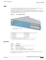
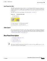
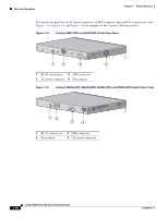
Chapter 1 Product Overview Rear Panel Description Dual-Purpose Port LEDs The LEDs on a dual-purpose port (see Figure 1-13) show whether the RJ-45 connector is connected or whether an SFP module is installed. You can configure each port as either a 10/100/1000 port through the RJ-45 connector or as an SFP module, but not both at the same time. The LEDs show how the port is being used. The LED colors have the same meaning as described in Table 1-4 to Table 1-6. Figure 1-13 Dual-Purpose Port LEDs 1 234 1 1 RJ-45 connector 3 SFP module port LED 2 RJ-45 port LED 4 SFP module slot Cable Guard You can order an optional cable guard to secure cables to the front of the switch and prevent them from being accidentally removed. To order a cable guard (CBLGRD-C3560-12PC or CBLGRD-C3560-8PC), contact your Cisco representative. The cable guard serves a different purpose than the cable guide (see "Attaching the Cable Guide" section on page 2-11). Rear Panel Description • Internal Power Supply, page 1-18 • Cisco RPS, page 1-19 • Console Port, page 1-19 • Security Slots, page 1-20 Note The Catalyst 3560-8PC and the Catalyst 3560-12PC-S switches do not have an RPS connector or a fan. The switch console port is on the front panel. OL-6337-07 Catalyst 3560 Switch Hardware Installation Guide 1-15
-
 1
1 -
2
-
3
-
4
-
5
-
6
-
7
-
8
-
9
-
10
-
11
-
12
-
13
-
14
-
15
-
16
-
17
-
18
-
19
-
 20
20 -
 21
21 -
 22
22 -
 23
23 -
 24
24 -
 25
25 -
 26
26 -
 27
27 -
 28
28 -
 29
29 -
 30
30 -
31
-
32
-
33
-
34
-
35
-
36
-
37
-
38
-
39
-
40
-
41
-
42
-
43
-
44
-
45
-
46
-
47
-
48
-
49
-
50
-
51
-
52
-
53
-
54
-
55
-
56
-
57
-
58
-
59
-
60
-
61
-
62
-
63
-
64
-
65
-
66
-
67
-
68
-
69
-
70
-
71
-
72
-
73
-
74
-
75
-
76
-
77
-
78
-
79
-
80
-
81
-
82
-
83
-
84
-
85
-
86
-
87
-
88
-
89
-
90
-
91
-
92
-
93
-
94
-
95
-
96
-
97
-
98
-
99
-
100
-
101
-
102
-
103
-
104
-
105
-
106
-
107
-
108
-
109
-
110
-
111
-
112
-
113
-
114
-
115
-
116
-
117
-
118
-
119
-
120
 |
 |
