Cisco WS-C3560E-48PD-SF Hardware Installation Guide - Page 16
Gigabit Ethernet Switch Front Panel Descriptions, Catalyst 3560-12PC-S Switch Front Panel
 |
View all Cisco WS-C3560E-48PD-SF manuals
Add to My Manuals
Save this manual to your list of manuals |
Page 16 highlights
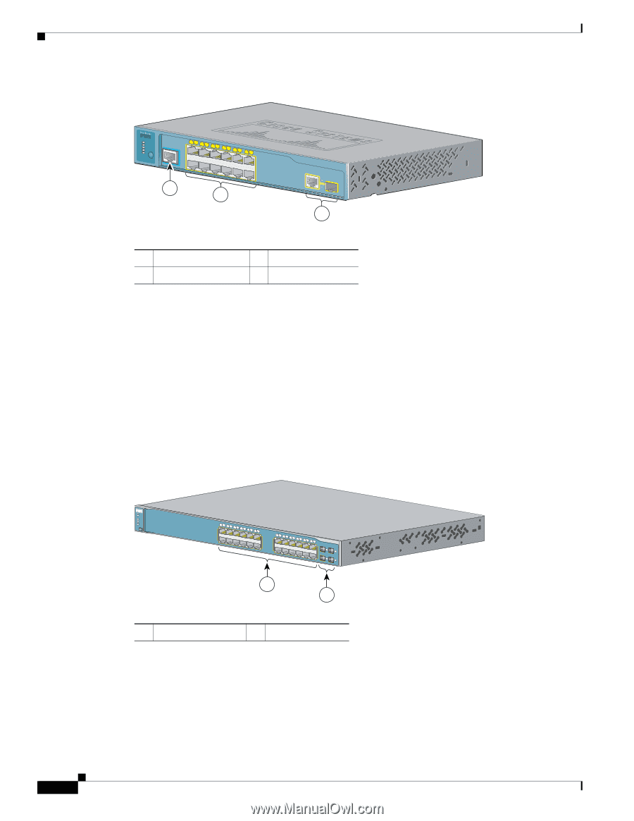
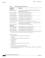
Front Panel Description Figure 1-6 Catalyst 3560-12PC-S Switch Front Panel Chapter 1 Product Overview 250606 SYST STAT DPLX SPD PoE MODE CONSOLE 12 34 56 78 9 10 11 12 1 2 Catalyst 3560 SERIESPoE-12 1 3 1 Console port 2 10/100 PoE ports 3 Dual-purpose port Gigabit Ethernet Switch Front Panel Descriptions • Catalyst 3560G-24PS Switch Front Panel, Figure 1-7 on page 1-6 • Catalyst 3560G-24TS Switch Front Panel, Figure 1-8 on page 1-7 • Catalyst 3560G-48PS Switch Front Panel, Figure 1-9 on page 1-7 • Catalyst 3560G-48TS Switch Front Panel, Figure 1-10 on page 1-8 The 10/100/1000 PoE ports on the Catalyst 3560G-24PS switch are grouped in pairs. The first member of the pair (port 1) is above the second member (port 2) on the left, as shown in Figure 1-7. Port 3 is above port 4, and so on. The SFP module slots are numbered 25 to 28. Figure 1-7 Catalyst 3560G-24PS Switch Front Panel 119676 SYST RPS STAT DUPLX SPEED PoE MODE 12 1X 34 56 78 9 10 11 12 11X 2X 12X 13 14 13X 15 16 17 18 19 20 21 22 23 24 Catalyst 3560G SERIES PoE-24 23X 25 14X 27 24X 26 28 1 2 1 10/100/1000 ports 2 SFP module slots Catalyst 3560 Switch Hardware Installation Guide 1-6 OL-6337-07
-
 1
1 -
2
-
3
-
4
-
5
-
6
-
7
-
8
-
9
-
10
-
 11
11 -
 12
12 -
 13
13 -
 14
14 -
 15
15 -
 16
16 -
 17
17 -
 18
18 -
 19
19 -
 20
20 -
 21
21 -
22
-
23
-
24
-
25
-
26
-
27
-
28
-
29
-
30
-
31
-
32
-
33
-
34
-
35
-
36
-
37
-
38
-
39
-
40
-
41
-
42
-
43
-
44
-
45
-
46
-
47
-
48
-
49
-
50
-
51
-
52
-
53
-
54
-
55
-
56
-
57
-
58
-
59
-
60
-
61
-
62
-
63
-
64
-
65
-
66
-
67
-
68
-
69
-
70
-
71
-
72
-
73
-
74
-
75
-
76
-
77
-
78
-
79
-
80
-
81
-
82
-
83
-
84
-
85
-
86
-
87
-
88
-
89
-
90
-
91
-
92
-
93
-
94
-
95
-
96
-
97
-
98
-
99
-
100
-
101
-
102
-
103
-
104
-
105
-
106
-
107
-
108
-
109
-
110
-
111
-
112
-
113
-
114
-
115
-
116
-
117
-
118
-
119
-
120
 |
 |