Cisco WS-C3560E-48PD-SF Hardware Installation Guide - Page 21
LEDs, System LED
 |
View all Cisco WS-C3560E-48PD-SF manuals
Add to My Manuals
Save this manual to your list of manuals |
Page 21 highlights
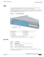
Chapter 1 Product Overview Front Panel Description LEDs You can use the switch LEDs to monitor switch activity and its performance. Figure 1-12 shows the switch LEDs and the Mode button that you use to select one of the port modes. All the LEDs described here are visible in the embedded device manager and Network Assistant GUIs. The switch online help describes how to use the device manager or Network Assistant to configure and monitor individual switches and switch clusters. Figure 1-12 Catalyst 3560 Switch LEDs SYST RPS STAT DUPLX SPEED PoE MODE 12345 67 8 12 1X 34 56 78 9 10 11 12 11X 2X 12X 97913 System LED 1 Mode button 2 PoE LED1 5 Status LED 6 RPS LED2 3 Speed LED 7 System LED 4 Duplex LED 8 Port LEDs 1. The PoE LED is only on the Catalyst 3560 PoE switches. 2. The Catalyst 3560-8PC and the Catalyst 3560-12PC-S switches do not have an RPS LED. Table 1-2 Color Off Green Amber System LED System Status System is not powered on. System is operating normally. System is receiving power but is not functioning properly. For information on the System LED colors during the power-on self-test (POST), see the "Verifying Switch Operation" section on page 2-6. OL-6337-07 Catalyst 3560 Switch Hardware Installation Guide 1-11
-
 1
1 -
2
-
3
-
4
-
5
-
6
-
7
-
8
-
9
-
10
-
11
-
12
-
13
-
14
-
15
-
 16
16 -
 17
17 -
 18
18 -
 19
19 -
 20
20 -
 21
21 -
 22
22 -
 23
23 -
 24
24 -
 25
25 -
 26
26 -
27
-
28
-
29
-
30
-
31
-
32
-
33
-
34
-
35
-
36
-
37
-
38
-
39
-
40
-
41
-
42
-
43
-
44
-
45
-
46
-
47
-
48
-
49
-
50
-
51
-
52
-
53
-
54
-
55
-
56
-
57
-
58
-
59
-
60
-
61
-
62
-
63
-
64
-
65
-
66
-
67
-
68
-
69
-
70
-
71
-
72
-
73
-
74
-
75
-
76
-
77
-
78
-
79
-
80
-
81
-
82
-
83
-
84
-
85
-
86
-
87
-
88
-
89
-
90
-
91
-
92
-
93
-
94
-
95
-
96
-
97
-
98
-
99
-
100
-
101
-
102
-
103
-
104
-
105
-
106
-
107
-
108
-
109
-
110
-
111
-
112
-
113
-
114
-
115
-
116
-
117
-
118
-
119
-
120
 |
 |
