Cisco WS-C3560E-48PD-SF Hardware Installation Guide - Page 13
Front Panel Description, Fast Ethernet Switch Front Panel Descriptions
 |
View all Cisco WS-C3560E-48PD-SF manuals
Add to My Manuals
Save this manual to your list of manuals |
Page 13 highlights
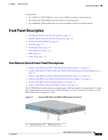
Chapter 1 Product Overview Front Panel Description Configuration: • For 10/100 and 10/100/1000 ports, the speed and duplex settings are autonegotiated. • For 10/100 and 10/100/1000 ports, PoE settings are autonegotiated. • For 1000BASE-T SFP module ports, the speed and duplex settings are autonegotiated. Front Panel Description • Fast Ethernet Switch Front Panel Descriptions, page 1-3 • Gigabit Ethernet Switch Front Panel Descriptions, page 1-6 • 10/100 and 10/100/1000 Ports, page 1-8 • PoE Ports, page 1-9 • SFP Module Slots, page 1-10 • Dual-Purpose Port, page 1-10 • LEDs, page 1-11 • Cable Guard, page 1-15 Fast Ethernet Switch Front Panel Descriptions • Catalyst 3560-24PS and 3560V2-24PS Switch Front Panel, Figure 1-1 on page 1-3 • Catalyst 3560-24TS-S, 3560V2-24TS, and 3560V2-24TS-SD Switch Front Panel, Figure 1-2 on page 1-4 • Catalyst 3560-48PS and 3560V2-48PS Switch Front Panel, Figure 1-3 on page 1-4 • Catalyst 3560-48TS-S and 3560V2-48TS Switch Front Panel, Figure 1-4 on page 1-5 • Catalyst 3560-8PC Switch Front Panel, Figure 1-5 on page 1-5 • Catalyst 3560-12PC-S Switch Front Panel, Figure 1-6 on page 1-6 The 10/100 PoE ports on the switch are grouped in pairs. The first member of the pair (port 1) is above the second member (port 2) on the left, as shown in Figure 1-1. Port 3 is above port 4, and so on. The SFP module slots are numbered 1 and 2. Figure 1-1 Catalyst 3560-24PS and 3560V2-24PS Switch Front Panel OL-6337-07 97912 SYST RPS STAT DUPLX SPEED PoE MODE 12 1X 34 56 78 9 10 11 12 11X 2X 12X 13 14 13X 15 16 17 18 19 20 21 22 23 24 Catalyst 3560 SERIES PoE-24 23X 14X 24X 1 2 1 2 1 10/100 PoE ports 2 SFP module slots Catalyst 3560 Switch Hardware Installation Guide 1-3
-
 1
1 -
2
-
3
-
4
-
5
-
6
-
7
-
 8
8 -
 9
9 -
 10
10 -
 11
11 -
 12
12 -
 13
13 -
 14
14 -
 15
15 -
 16
16 -
 17
17 -
 18
18 -
19
-
20
-
21
-
22
-
23
-
24
-
25
-
26
-
27
-
28
-
29
-
30
-
31
-
32
-
33
-
34
-
35
-
36
-
37
-
38
-
39
-
40
-
41
-
42
-
43
-
44
-
45
-
46
-
47
-
48
-
49
-
50
-
51
-
52
-
53
-
54
-
55
-
56
-
57
-
58
-
59
-
60
-
61
-
62
-
63
-
64
-
65
-
66
-
67
-
68
-
69
-
70
-
71
-
72
-
73
-
74
-
75
-
76
-
77
-
78
-
79
-
80
-
81
-
82
-
83
-
84
-
85
-
86
-
87
-
88
-
89
-
90
-
91
-
92
-
93
-
94
-
95
-
96
-
97
-
98
-
99
-
100
-
101
-
102
-
103
-
104
-
105
-
106
-
107
-
108
-
109
-
110
-
111
-
112
-
113
-
114
-
115
-
116
-
117
-
118
-
119
-
120
 |
 |
