Cisco WS-C3560E-48PD-SF Hardware Installation Guide - Page 93
Connector and Cable Specifications, 10/100 and 10/100/1000 Ports
 |
View all Cisco WS-C3560E-48PD-SF manuals
Add to My Manuals
Save this manual to your list of manuals |
Page 93 highlights
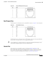
B A P P E N D I X Connector and Cable Specifications This appendix describes the Catalyst 3560 switch ports and the cables and adapters that you use to connect the switch to other devices and includes these sections: • "Connector Specifications" section on page B-1 • "Cable and Adapter Specifications" section on page B-4 Connector Specifications • 10/100 and 10/100/1000 Ports, page B-1 • SFP Module Ports, page B-2 • Dual-Purpose Ports, page B-3 • Console Port, page B-3 10/100 and 10/100/1000 Ports The 10/100 and 10/100/1000 Ethernet ports use standard RJ-45 connectors and Ethernet pinouts with internal crossovers. These ports have the send (TD) and receive (RD) signals internally crossed so that a twisted-pair straight-through cable and adapter can be attached to the port. Figure B-1 shows the pinout for a 10/100 port. OL-6337-07 Catalyst 3560 Switch Hardware Installation Guide B-1
-
 1
1 -
2
-
3
-
4
-
5
-
6
-
7
-
8
-
9
-
10
-
11
-
12
-
13
-
14
-
15
-
16
-
17
-
18
-
19
-
20
-
21
-
22
-
23
-
24
-
25
-
26
-
27
-
28
-
29
-
30
-
31
-
32
-
33
-
34
-
35
-
36
-
37
-
38
-
39
-
40
-
41
-
42
-
43
-
44
-
45
-
46
-
47
-
48
-
49
-
50
-
51
-
52
-
53
-
54
-
55
-
56
-
57
-
58
-
59
-
60
-
61
-
62
-
63
-
64
-
65
-
66
-
67
-
68
-
69
-
70
-
71
-
72
-
73
-
74
-
75
-
76
-
77
-
78
-
79
-
80
-
81
-
82
-
83
-
84
-
85
-
86
-
87
-
 88
88 -
 89
89 -
 90
90 -
 91
91 -
 92
92 -
 93
93 -
 94
94 -
 95
95 -
 96
96 -
 97
97 -
 98
98 -
99
-
100
-
101
-
102
-
103
-
104
-
105
-
106
-
107
-
108
-
109
-
110
-
111
-
112
-
113
-
114
-
115
-
116
-
117
-
118
-
119
-
120
 |
 |
