Cisco WS-C3560E-48PD-SF Hardware Installation Guide - Page 110
Step 2, D-2, Connecting a Switch to a PC
 |
View all Cisco WS-C3560E-48PD-SF manuals
Add to My Manuals
Save this manual to your list of manuals |
Page 110 highlights
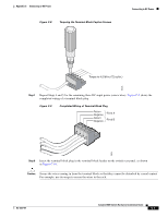
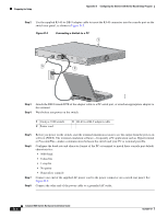
Preparing for Setup Appendix D Configuring the Switch with the CLI-Based Setup Program Step 2 Use the supplied RJ-45-to-DB-9 adapter cable to insert the RJ-45 connector into the console port on the switch rear panel, as shown in Figure D-2. Figure D-2 Connecting a Switch to a PC 1 CONSOLE 3 RATING 5.0A1-20.05-A2,0500V-6~0 HZ [email protected]@YMUO7A.TL8EA 2 97934 Step 3 Step 4 Attach the DB-9 female DTE of the adapter cable to a PC serial port, or attach an appropriate adapter to the terminal. Wait before you power on the switch. 1 Catalyst 3560 switch 2 Power cord 3 RJ-45-to-DB-9 adapter cable Step 5 Step 6 Step 7 Step 8 Before you power on the switch, start the terminal emulation session to see the output from the power-on self-test (POST). The terminal-emulation software-frequently a PC application such as Hyperterminal or ProcommPlus-makes communication between the switch and your PC or terminal possible. Configure the baud rate and character format of the PC or terminal to match these console port default characteristics: • 9600 baud • 8 data bits • 1 stop bit • No parity • None (flow control) Connect one end of the supplied AC power cord to the power connector on a switch rear panel. See Figure D-2. Connect the other end of the power cable to a grounded AC outlet. Catalyst 3560 Switch Hardware Installation Guide D-2 OL-6337-07
-
 1
1 -
2
-
3
-
4
-
5
-
6
-
7
-
8
-
9
-
10
-
11
-
12
-
13
-
14
-
15
-
16
-
17
-
18
-
19
-
20
-
21
-
22
-
23
-
24
-
25
-
26
-
27
-
28
-
29
-
30
-
31
-
32
-
33
-
34
-
35
-
36
-
37
-
38
-
39
-
40
-
41
-
42
-
43
-
44
-
45
-
46
-
47
-
48
-
49
-
50
-
51
-
52
-
53
-
54
-
55
-
56
-
57
-
58
-
59
-
60
-
61
-
62
-
63
-
64
-
65
-
66
-
67
-
68
-
69
-
70
-
71
-
72
-
73
-
74
-
75
-
76
-
77
-
78
-
79
-
80
-
81
-
82
-
83
-
84
-
85
-
86
-
87
-
88
-
89
-
90
-
91
-
92
-
93
-
94
-
95
-
96
-
97
-
98
-
99
-
100
-
101
-
102
-
103
-
104
-
 105
105 -
 106
106 -
 107
107 -
 108
108 -
 109
109 -
 110
110 -
 111
111 -
 112
112 -
 113
113 -
 114
114 -
 115
115 -
116
-
117
-
118
-
119
-
120
 |
 |
