Cisco WS-C3560E-48PD-SF Hardware Installation Guide - Page 50
Inserting and Removing the SFP Module Patch Cable
 |
View all Cisco WS-C3560E-48PD-SF manuals
Add to My Manuals
Save this manual to your list of manuals |
Page 50 highlights
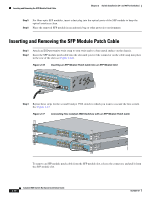
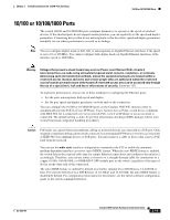
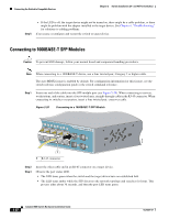
Inserting and Removing the SFP Module Patch Cable Chapter 2 Switch Installation (24- and 48-Port Switches) Step 5 Step 6 For fiber-optic SFP modules, insert a dust plug into the optical ports of the SFP module to keep the optical interfaces clean. Place the removed SFP module in an antistatic bag or other protective environment. Inserting and Removing the SFP Module Patch Cable Step 1 Step 2 Attach an ESD-preventive wrist strap to your wrist and to a bare metal surface on the chassis. Insert the SFP module patch cable into the slot until you feel the connector on the cable snap into place in the rear of the slot (see Figure 2-16). Figure 2-16 Inserting an SFP Module Patch Cable into an SFP Module Slot 13 14 13X 15 16 17 18 19 20 21 22 23 24 23X Catalyst 3560 SERIES 14X 24X 1 2 126810 Step 3 Repeat these steps for the second Catalyst 3560 switch to which you want to cascade the first switch. See Figure 2-17. Figure 2-17 Connecting Two Catalyst 3560 Switches with an SFP Module Patch Cable SYST RPS STAT DUPLX SPEED MODE SYST RPS STAT DUPLX SPEED MODE 12 1X 34 56 78 9 10 11 12 11X 2X 12X 12 1X 34 56 78 9 10 11 12 11X 2X 12X 13 14 13X 15 16 17 18 19 20 21 22 23 24 23X Catalyst 3560 SERIES 14X 24X 1 2 13 14 13X 15 16 17 18 19 20 21 22 23 24 23X Catalyst 3560 SERIES 14X 24X 1 2 126811 To remove an SFP module patch cable from the SFP module slot, release the connector, and pull it from the SFP module slot. 2-18 Catalyst 3560 Switch Hardware Installation Guide OL-6337-07
-
 1
1 -
2
-
3
-
4
-
5
-
6
-
7
-
8
-
9
-
10
-
11
-
12
-
13
-
14
-
15
-
16
-
17
-
18
-
19
-
20
-
21
-
22
-
23
-
24
-
25
-
26
-
27
-
28
-
29
-
30
-
31
-
32
-
33
-
34
-
35
-
36
-
37
-
38
-
39
-
40
-
41
-
42
-
43
-
44
-
 45
45 -
 46
46 -
 47
47 -
 48
48 -
 49
49 -
 50
50 -
 51
51 -
 52
52 -
 53
53 -
 54
54 -
 55
55 -
56
-
57
-
58
-
59
-
60
-
61
-
62
-
63
-
64
-
65
-
66
-
67
-
68
-
69
-
70
-
71
-
72
-
73
-
74
-
75
-
76
-
77
-
78
-
79
-
80
-
81
-
82
-
83
-
84
-
85
-
86
-
87
-
88
-
89
-
90
-
91
-
92
-
93
-
94
-
95
-
96
-
97
-
98
-
99
-
100
-
101
-
102
-
103
-
104
-
105
-
106
-
107
-
108
-
109
-
110
-
111
-
112
-
113
-
114
-
115
-
116
-
117
-
118
-
119
-
120
 |
 |
