Dell Vostro 200 Owner's Manual - Page 112
Memory Installation Guidelines, If the memory modules are - memory capacity
 |
View all Dell Vostro 200 manuals
Add to My Manuals
Save this manual to your list of manuals |
Page 112 highlights
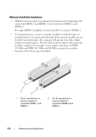
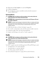
Memory Installation Guidelines • DIMM connectors must be populated in numerical order beginning with connectors DIMM_1 and DIMM_3, then connectors DIMM_2 and DIMM_4. If a single DIMM is installed, you must install it in connector DIMM_1. • For best performance, memory modules should be installed in pairs of matched memory size, speed, and technology. If the memory modules are not installed in matched pairs, the computer will operate, but with a slight reduction in performance. (See the label on the module to determine the module's capacity.) For example, if you install a mixed pair of DDR2 533-MHz and DDR2 667-MHz and 800 MHz memory, the modules function at the slowest speed installed. 1 2 1 Pair A: matched pair of memory modules in connectors DIMM_1 and DIMM_2 2 Pair B: matched pair of memory modules in connectors DIMM_3 and DIMM_4 112 Removing and Installing Parts
-
 1
1 -
2
-
3
-
4
-
5
-
6
-
7
-
8
-
9
-
10
-
11
-
12
-
13
-
14
-
15
-
16
-
17
-
18
-
19
-
20
-
21
-
22
-
23
-
24
-
25
-
26
-
27
-
28
-
29
-
30
-
31
-
32
-
33
-
34
-
35
-
36
-
37
-
38
-
39
-
40
-
41
-
42
-
43
-
44
-
45
-
46
-
47
-
48
-
49
-
50
-
51
-
52
-
53
-
54
-
55
-
56
-
57
-
58
-
59
-
60
-
61
-
62
-
63
-
64
-
65
-
66
-
67
-
68
-
69
-
70
-
71
-
72
-
73
-
74
-
75
-
76
-
77
-
78
-
79
-
80
-
81
-
82
-
83
-
84
-
85
-
86
-
87
-
88
-
89
-
90
-
91
-
92
-
93
-
94
-
95
-
96
-
97
-
98
-
99
-
100
-
101
-
102
-
103
-
104
-
105
-
106
-
 107
107 -
 108
108 -
 109
109 -
 110
110 -
 111
111 -
 112
112 -
 113
113 -
 114
114 -
 115
115 -
 116
116 -
 117
117 -
118
-
119
-
120
-
121
-
122
-
123
-
124
-
125
-
126
-
127
-
128
-
129
-
130
-
131
-
132
-
133
-
134
-
135
-
136
-
137
-
138
-
139
-
140
-
141
-
142
-
143
-
144
-
145
-
146
-
147
-
148
-
149
-
150
-
151
-
152
-
153
-
154
-
155
-
156
-
157
-
158
-
159
-
160
-
161
-
162
-
163
-
164
-
165
-
166
-
167
-
168
-
169
-
170
-
171
-
172
-
173
-
174
-
175
-
176
-
177
-
178
-
179
-
180
-
181
-
182
-
183
-
184
-
185
-
186
-
187
-
188
-
189
-
190
-
191
-
192
-
193
-
194
-
195
-
196
-
197
-
198
-
199
-
200
-
201
-
202
-
203
-
204
-
205
-
206
-
207
-
208
-
209
-
210
-
211
-
212
-
213
-
214
 |
 |
