Dell Vostro 200 Owner's Manual - Page 146
Replace the computer cover see Replacing the Computer Cover
 |
View all Dell Vostro 200 manuals
Add to My Manuals
Save this manual to your list of manuals |
Page 146 highlights
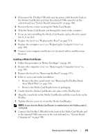
1 2 6 5 3 4 1 optical drive 4 system board connector 2 data cable 5 screw holes in the optical drive bay (2) 3 power cable 6 screws (2) 9 Replace the bezel (see "Replacing the Bezel" on page 125). 10 Replace the computer cover (see "Replacing the Computer Cover" on page 166). NOTICE: To connect a network cable, first plug the cable into the network device and then plug it into the computer. 11 Connect your computer and devices to their electrical outlets, and turn them on. See the documentation that came with the drive for instructions on installing any software required for drive operation. 146 Removing and Installing Parts
-
 1
1 -
2
-
3
-
4
-
5
-
6
-
7
-
8
-
9
-
10
-
11
-
12
-
13
-
14
-
15
-
16
-
17
-
18
-
19
-
20
-
21
-
22
-
23
-
24
-
25
-
26
-
27
-
28
-
29
-
30
-
31
-
32
-
33
-
34
-
35
-
36
-
37
-
38
-
39
-
40
-
41
-
42
-
43
-
44
-
45
-
46
-
47
-
48
-
49
-
50
-
51
-
52
-
53
-
54
-
55
-
56
-
57
-
58
-
59
-
60
-
61
-
62
-
63
-
64
-
65
-
66
-
67
-
68
-
69
-
70
-
71
-
72
-
73
-
74
-
75
-
76
-
77
-
78
-
79
-
80
-
81
-
82
-
83
-
84
-
85
-
86
-
87
-
88
-
89
-
90
-
91
-
92
-
93
-
94
-
95
-
96
-
97
-
98
-
99
-
100
-
101
-
102
-
103
-
104
-
105
-
106
-
107
-
108
-
109
-
110
-
111
-
112
-
113
-
114
-
115
-
116
-
117
-
118
-
119
-
120
-
121
-
122
-
123
-
124
-
125
-
126
-
127
-
128
-
129
-
130
-
131
-
132
-
133
-
134
-
135
-
136
-
137
-
138
-
139
-
140
-
 141
141 -
 142
142 -
 143
143 -
 144
144 -
 145
145 -
 146
146 -
 147
147 -
 148
148 -
 149
149 -
 150
150 -
 151
151 -
152
-
153
-
154
-
155
-
156
-
157
-
158
-
159
-
160
-
161
-
162
-
163
-
164
-
165
-
166
-
167
-
168
-
169
-
170
-
171
-
172
-
173
-
174
-
175
-
176
-
177
-
178
-
179
-
180
-
181
-
182
-
183
-
184
-
185
-
186
-
187
-
188
-
189
-
190
-
191
-
192
-
193
-
194
-
195
-
196
-
197
-
198
-
199
-
200
-
201
-
202
-
203
-
204
-
205
-
206
-
207
-
208
-
209
-
210
-
211
-
212
-
213
-
214
 |
 |

146
Removing and Installing Parts
9
Replace the bezel (see "Replacing the Bezel" on page 125).
10
Replace the computer cover (see "Replacing the Computer Cover" on
page 166).
NOTICE:
To connect a network cable, first plug the cable into the network device
and then plug it into the computer.
11
Connect your computer and devices to their electrical outlets, and turn
them on.
See the documentation that came with the drive for instructions on
installing any software required for drive operation.
1
optical drive
2
data cable
3
power cable
4
system board
connector
5
screw holes in the
optical drive bay (2)
6
screws (2)
1
2
4
3
6
5