Dell Vostro 200 Owner's Manual - Page 137
Check all cable connections, and fold cables out of the way to avoid
 |
View all Dell Vostro 200 manuals
Add to My Manuals
Save this manual to your list of manuals |
Page 137 highlights
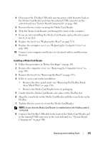
7 Tighten the two screws to secure the floppy drive. 8 Attach the power and data cables to the floppy drive. 9 Connect the other end of the data cable to the connector labeled "FLOPPY" on the system board (see "System Board Components" on page 106) and route the cable through the clip on the shroud. 6 5 1 2 3 4 1 floppy drive 4 system board connector 2 data cable 5 screws (2) 3 power cable 6 screw holes in the floppy drive 10 Check all cable connections, and fold cables out of the way to avoid blocking airflow between the fan and cooling vents. 11 Replace the bezel (see "Replacing the Bezel" on page 125). Removing and Installing Parts 137
-
 1
1 -
2
-
3
-
4
-
5
-
6
-
7
-
8
-
9
-
10
-
11
-
12
-
13
-
14
-
15
-
16
-
17
-
18
-
19
-
20
-
21
-
22
-
23
-
24
-
25
-
26
-
27
-
28
-
29
-
30
-
31
-
32
-
33
-
34
-
35
-
36
-
37
-
38
-
39
-
40
-
41
-
42
-
43
-
44
-
45
-
46
-
47
-
48
-
49
-
50
-
51
-
52
-
53
-
54
-
55
-
56
-
57
-
58
-
59
-
60
-
61
-
62
-
63
-
64
-
65
-
66
-
67
-
68
-
69
-
70
-
71
-
72
-
73
-
74
-
75
-
76
-
77
-
78
-
79
-
80
-
81
-
82
-
83
-
84
-
85
-
86
-
87
-
88
-
89
-
90
-
91
-
92
-
93
-
94
-
95
-
96
-
97
-
98
-
99
-
100
-
101
-
102
-
103
-
104
-
105
-
106
-
107
-
108
-
109
-
110
-
111
-
112
-
113
-
114
-
115
-
116
-
117
-
118
-
119
-
120
-
121
-
122
-
123
-
124
-
125
-
126
-
127
-
128
-
129
-
130
-
131
-
 132
132 -
 133
133 -
 134
134 -
 135
135 -
 136
136 -
 137
137 -
 138
138 -
 139
139 -
 140
140 -
 141
141 -
 142
142 -
143
-
144
-
145
-
146
-
147
-
148
-
149
-
150
-
151
-
152
-
153
-
154
-
155
-
156
-
157
-
158
-
159
-
160
-
161
-
162
-
163
-
164
-
165
-
166
-
167
-
168
-
169
-
170
-
171
-
172
-
173
-
174
-
175
-
176
-
177
-
178
-
179
-
180
-
181
-
182
-
183
-
184
-
185
-
186
-
187
-
188
-
189
-
190
-
191
-
192
-
193
-
194
-
195
-
196
-
197
-
198
-
199
-
200
-
201
-
202
-
203
-
204
-
205
-
206
-
207
-
208
-
209
-
210
-
211
-
212
-
213
-
214
 |
 |

Removing and Installing Parts
137
7
Tighten the two screws to secure the floppy drive.
8
Attach the power and data cables to the floppy drive.
9
Connect the other end of the data cable to the connector labeled
"FLOPPY" on the system board (see "System Board Components" on
page 106) and route the cable through the clip on the shroud.
10
Check all cable connections, and fold cables out of the way to avoid
blocking airflow between the fan and cooling vents.
11
Replace the bezel (see "Replacing the Bezel" on page 125).
1
floppy drive
2
data cable
3
power cable
4
system board
connector
5
screws (2)
6
screw holes in the
floppy drive
2
4
3
1
5
6