HP 450c HP DesignJet 430/450C/488CA Printer - UserÂ’s Guide - Page 162
Interface specifications
 |
View all HP 450c manuals
Add to My Manuals
Save this manual to your list of manuals |
Page 162 highlights
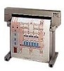
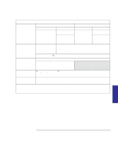
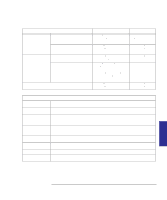
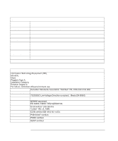
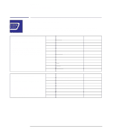
Reference Interface specifications Interface specifications Below are the parallel and serial interface specifications. On the following page are the pin configurations for the most common HP cables referenced on page 10-11. Parallel (Centronics) Interface The connector on the printer is 36-pin female. Most existing parallel cables support IEEE-1284-compatible communication, but, for use with this printer, the cable must meet the specification in this table. Pin Wire/Signal Name 1 Strobe 2 ... 9 D0 ... D7 (data lines) 11 Busy 12 PError 13 Select (SelectOut) 14 AutoFd 16 GND 19 ... 30 GND 31 Init 32 Fault 36 SelectIn Source computer both printer printer printer computer computer printer computer Serial (RS-232-C) Interface The connector on the printer is 25-pin female. The printer is configured as DTE (data terminal equipment). Data is transmitted on Pin 2 and received on Pin 3. Pin Wire/Signal Name 1 Protective Ground 2 Transmitted Data 3 Received Data 4 Request to Send 6 Data Set Ready 7 Signal Ground 20 Data Terminal Ready Source DTE DCE DTE DCE DTE 10-8
-
 1
1 -
2
-
3
-
4
-
5
-
6
-
7
-
8
-
9
-
10
-
11
-
12
-
13
-
14
-
15
-
16
-
17
-
18
-
19
-
20
-
21
-
22
-
23
-
24
-
25
-
26
-
27
-
28
-
29
-
30
-
31
-
32
-
33
-
34
-
35
-
36
-
37
-
38
-
39
-
40
-
41
-
42
-
43
-
44
-
45
-
46
-
47
-
48
-
49
-
50
-
51
-
52
-
53
-
54
-
55
-
56
-
57
-
58
-
59
-
60
-
61
-
62
-
63
-
64
-
65
-
66
-
67
-
68
-
69
-
70
-
71
-
72
-
73
-
74
-
75
-
76
-
77
-
78
-
79
-
80
-
81
-
82
-
83
-
84
-
85
-
86
-
87
-
88
-
89
-
90
-
91
-
92
-
93
-
94
-
95
-
96
-
97
-
98
-
99
-
100
-
101
-
102
-
103
-
104
-
105
-
106
-
107
-
108
-
109
-
110
-
111
-
112
-
113
-
114
-
115
-
116
-
117
-
118
-
119
-
120
-
121
-
122
-
123
-
124
-
125
-
126
-
127
-
128
-
129
-
130
-
131
-
132
-
133
-
134
-
135
-
136
-
137
-
138
-
139
-
140
-
141
-
142
-
143
-
144
-
145
-
146
-
147
-
148
-
149
-
150
-
151
-
152
-
153
-
154
-
155
-
156
-
 157
157 -
 158
158 -
 159
159 -
 160
160 -
 161
161 -
 162
162 -
 163
163 -
 164
164 -
 165
165 -
 166
166 -
 167
167 -
168
-
169
-
170
-
171
-
172
-
173
-
174
-
175
-
176
-
177
-
178
-
179
-
180
-
181
-
182
-
183
-
184
-
185
-
186
-
187
-
188
-
189
-
190
-
191
-
192
-
193
 |
 |