HP LaserJet 5p/mp Service Manual - Page 153
Tray 1 Pickup Assembly Locations.
 |
View all HP LaserJet 5p/mp manuals
Add to My Manuals
Save this manual to your list of manuals |
Page 153 highlights
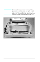
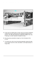
HP LaserJet 5P/5MP, 6P/6MP Printer Service Supplement Removal and Replacement Figure 22 Tray 1 Pickup Assembly Locations. 5. Press the two release tabs on either side of the pickup assembly (callout 3 in Figure 19) and pull the assembly away from the printer. (The left side release tab is partially hidden from view. Pressing in on both sides will release the tabs.) 6. Pull the pickup assembly straight out from the back of the printer. 7. To remove the roller from the pickup assembly, grasp the tabs on the right end of the roller and slide it to the right (shown in Figure 23). 50
-
 1
1 -
2
-
3
-
4
-
5
-
6
-
7
-
8
-
9
-
10
-
11
-
12
-
13
-
14
-
15
-
16
-
17
-
18
-
19
-
20
-
21
-
22
-
23
-
24
-
25
-
26
-
27
-
28
-
29
-
30
-
31
-
32
-
33
-
34
-
35
-
36
-
37
-
38
-
39
-
40
-
41
-
42
-
43
-
44
-
45
-
46
-
47
-
48
-
49
-
50
-
51
-
52
-
53
-
54
-
55
-
56
-
57
-
58
-
59
-
60
-
61
-
62
-
63
-
64
-
65
-
66
-
67
-
68
-
69
-
70
-
71
-
72
-
73
-
74
-
75
-
76
-
77
-
78
-
79
-
80
-
81
-
82
-
83
-
84
-
85
-
86
-
87
-
88
-
89
-
90
-
91
-
92
-
93
-
94
-
95
-
96
-
97
-
98
-
99
-
100
-
101
-
102
-
103
-
104
-
105
-
106
-
107
-
108
-
109
-
110
-
111
-
112
-
113
-
114
-
115
-
116
-
117
-
118
-
119
-
120
-
121
-
122
-
123
-
124
-
125
-
126
-
127
-
128
-
129
-
130
-
131
-
132
-
133
-
134
-
135
-
136
-
137
-
138
-
139
-
140
-
141
-
142
-
143
-
144
-
145
-
146
-
147
-
 148
148 -
 149
149 -
 150
150 -
 151
151 -
 152
152 -
 153
153 -
 154
154 -
 155
155 -
 156
156 -
 157
157 -
 158
158 -
159
-
160
-
161
-
162
-
163
-
164
-
165
-
166
-
167
-
168
-
169
-
170
-
171
-
172
-
173
-
174
-
175
-
176
-
177
-
178
-
179
-
180
-
181
-
182
-
183
-
184
-
185
-
186
-
187
-
188
-
189
-
190
-
191
-
192
-
193
-
194
-
195
-
196
-
197
-
198
-
199
-
200
-
201
-
202
-
203
-
204
-
205
-
206
-
207
-
208
-
209
-
210
-
211
-
212
-
213
-
214
 |
 |

5.
Press the two release tabs on either side of the pickup assembly
(callout
3
in Figure 19) and pull the assembly away from the
printer. (The left side release tab is partially hidden from view.
Pressing in on both sides will release the tabs.)
6.
Pull the pickup assembly straight out from the back of the
printer.
7.
To remove the roller from the pickup assembly, grasp the tabs
on the right end of the roller and slide it to the right (shown in
Figure 23).
Figure 22
Tray 1 Pickup Assembly Locations.
HP LaserJet 5P/5MP, 6P/6MP Printer Service Supplement
Removal and Replacement
50