HP LaserJet 5p/mp Service Manual - Page 160
of the Combined Service Manual. Turn
 |
View all HP LaserJet 5p/mp manuals
Add to My Manuals
Save this manual to your list of manuals |
Page 160 highlights
HP LaserJet 5P/5MP, 6P/6MP Printer Service Supplement Removal and Replacement Figure 28 Grounding Spring screw location. 4. On the left side, remove the (2) screws that attach the grounding strap to the Gear Train Assembly (see callout 1 in Figure 6-36 of the Combined Service Manual). Turn the assembly upside-down before proceeding with further steps. 5. Remove the (5) self-tapping screws and the (1) machine screw with star washer from the bottom of the DC Controller Assembly. (See callouts 2 and 3 in Figure 6-36 in the Combined Service Manual.) 6. Lift the DC Controller Assembly away from the printer frame. 57
-
 1
1 -
2
-
3
-
4
-
5
-
6
-
7
-
8
-
9
-
10
-
11
-
12
-
13
-
14
-
15
-
16
-
17
-
18
-
19
-
20
-
21
-
22
-
23
-
24
-
25
-
26
-
27
-
28
-
29
-
30
-
31
-
32
-
33
-
34
-
35
-
36
-
37
-
38
-
39
-
40
-
41
-
42
-
43
-
44
-
45
-
46
-
47
-
48
-
49
-
50
-
51
-
52
-
53
-
54
-
55
-
56
-
57
-
58
-
59
-
60
-
61
-
62
-
63
-
64
-
65
-
66
-
67
-
68
-
69
-
70
-
71
-
72
-
73
-
74
-
75
-
76
-
77
-
78
-
79
-
80
-
81
-
82
-
83
-
84
-
85
-
86
-
87
-
88
-
89
-
90
-
91
-
92
-
93
-
94
-
95
-
96
-
97
-
98
-
99
-
100
-
101
-
102
-
103
-
104
-
105
-
106
-
107
-
108
-
109
-
110
-
111
-
112
-
113
-
114
-
115
-
116
-
117
-
118
-
119
-
120
-
121
-
122
-
123
-
124
-
125
-
126
-
127
-
128
-
129
-
130
-
131
-
132
-
133
-
134
-
135
-
136
-
137
-
138
-
139
-
140
-
141
-
142
-
143
-
144
-
145
-
146
-
147
-
148
-
149
-
150
-
151
-
152
-
153
-
154
-
 155
155 -
 156
156 -
 157
157 -
 158
158 -
 159
159 -
 160
160 -
 161
161 -
 162
162 -
 163
163 -
 164
164 -
 165
165 -
166
-
167
-
168
-
169
-
170
-
171
-
172
-
173
-
174
-
175
-
176
-
177
-
178
-
179
-
180
-
181
-
182
-
183
-
184
-
185
-
186
-
187
-
188
-
189
-
190
-
191
-
192
-
193
-
194
-
195
-
196
-
197
-
198
-
199
-
200
-
201
-
202
-
203
-
204
-
205
-
206
-
207
-
208
-
209
-
210
-
211
-
212
-
213
-
214
 |
 |

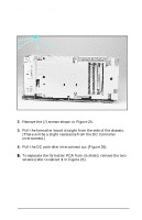
4.
On the left side, remove the (2) screws that attach the
grounding strap to the Gear Train Assembly (see callout 1 in
Figure 6-36 of the Combined Service Manual). Turn the
assembly upside-down before proceeding with further steps.
5.
Remove the (5) self-tapping screws and the (1) machine screw
with star washer from the bottom of the DC Controller
Assembly. (See callouts
2
and
3
in Figure 6-36 in the Combined
Service Manual.)
6.
Lift the DC Controller Assembly away from the printer frame.
Figure 28
Grounding Spring screw location.
HP LaserJet 5P/5MP, 6P/6MP Printer Service Supplement
Removal and Replacement
57