HP LaserJet 5p/mp Service Manual - Page 156
screws refer to callout
 |
View all HP LaserJet 5p/mp manuals
Add to My Manuals
Save this manual to your list of manuals |
Page 156 highlights
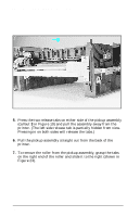
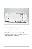
HP LaserJet 5P/5MP, 6P/6MP Printer Service Supplement Removal and Replacement Figure 25 Removing the formatter screws. 2. Remove the (7) screws shown in Figure 25. 3. Pull the formatter board straight from the side of the chassis. (There will be a slight resistance from the DC Controller interconnect.) 4. Pull the DC controller interconnect out (Figure 26). 5. To separate the formatter PCA from its shield, remove the two screws (refer to callout 1 in Figure 21). 53
-
 1
1 -
2
-
3
-
4
-
5
-
6
-
7
-
8
-
9
-
10
-
11
-
12
-
13
-
14
-
15
-
16
-
17
-
18
-
19
-
20
-
21
-
22
-
23
-
24
-
25
-
26
-
27
-
28
-
29
-
30
-
31
-
32
-
33
-
34
-
35
-
36
-
37
-
38
-
39
-
40
-
41
-
42
-
43
-
44
-
45
-
46
-
47
-
48
-
49
-
50
-
51
-
52
-
53
-
54
-
55
-
56
-
57
-
58
-
59
-
60
-
61
-
62
-
63
-
64
-
65
-
66
-
67
-
68
-
69
-
70
-
71
-
72
-
73
-
74
-
75
-
76
-
77
-
78
-
79
-
80
-
81
-
82
-
83
-
84
-
85
-
86
-
87
-
88
-
89
-
90
-
91
-
92
-
93
-
94
-
95
-
96
-
97
-
98
-
99
-
100
-
101
-
102
-
103
-
104
-
105
-
106
-
107
-
108
-
109
-
110
-
111
-
112
-
113
-
114
-
115
-
116
-
117
-
118
-
119
-
120
-
121
-
122
-
123
-
124
-
125
-
126
-
127
-
128
-
129
-
130
-
131
-
132
-
133
-
134
-
135
-
136
-
137
-
138
-
139
-
140
-
141
-
142
-
143
-
144
-
145
-
146
-
147
-
148
-
149
-
150
-
 151
151 -
 152
152 -
 153
153 -
 154
154 -
 155
155 -
 156
156 -
 157
157 -
 158
158 -
 159
159 -
 160
160 -
 161
161 -
162
-
163
-
164
-
165
-
166
-
167
-
168
-
169
-
170
-
171
-
172
-
173
-
174
-
175
-
176
-
177
-
178
-
179
-
180
-
181
-
182
-
183
-
184
-
185
-
186
-
187
-
188
-
189
-
190
-
191
-
192
-
193
-
194
-
195
-
196
-
197
-
198
-
199
-
200
-
201
-
202
-
203
-
204
-
205
-
206
-
207
-
208
-
209
-
210
-
211
-
212
-
213
-
214
 |
 |

2.
Remove the (7) screws shown in Figure 25.
3.
Pull the formatter board straight from the side of the chassis.
(There will be a slight resistance from the DC Controller
interconnect.)
4.
Pull the DC controller interconnect out (Figure 26).
5.
5.
To separate the formatter PCA from its shield, remove the two
screws (refer to callout
1
in Figure 21).
Figure 25
Removing the formatter screws.
HP LaserJet 5P/5MP, 6P/6MP Printer Service Supplement
Removal and Replacement
53