Invacare 3GAR Owners Manual 2 - Page 105
Wheelchairs with Vent Tray
 |
View all Invacare 3GAR manuals
Add to My Manuals
Save this manual to your list of manuals |
Page 105 highlights
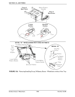
SECTION 10-BATTERIES Wheelchairs with Vent Tray ƽ WARNING Each battery weighs 51 pounds. Use proper lifting techniques (lift with your legs) to avoid injury. CAUTION Place the wheelchair in a well ventilated area where work can be performed without risking damage to carpeting or floor covering. NOTE: For this procedure, refer to FIGURE 10.7. Removing 1. Place the wheelchair in a well ventilated area where work can be performed without risking damage to carpeting or floor covering. 2. Verify the joystick On/Off switch is in the Off position. 3. Pull the battery box retainer Up over the end of the one connector battery box. 4. Slide one connector battery box along the sub-frame and remove from the wheelchair. 5. Slide the two connector battery box along the sub-frame and remove from the wheelchair. Installing 1. Place the wheelchair in a well ventilated area where work can be performed without risking damage to carpeting or floor covering. 2. Verify the joystick On/Off switch is in the Off position. 3. Secure the battery box carrying strap to the lid of the two connector battery box. 4. Place two connector battery box onto the battery sub-frame assembly with guide pins facing the inside of the wheelchair. 5. Slide the two connector battery box along the sub-frame until its guide pins are engaged in the sub-frame connector. NOTE: Visually inspect to ensure the connection is properly made. Connectors MUST be fully engaged. Battery Box Sub-Frame Base Frame Battery Box Retainer Bar Two Connector Battery Box One Connector Battery Box Battery Box Sub-Frame Two Connector Battery Box Base Frame One Connector Battery Box Battery Box Retainer Bar FIGURE 10.7 Wheelchairs with Vent Tray Part No 1134791 105 3G Storm Series® Wheelchairs
-
 1
1 -
2
-
3
-
4
-
5
-
6
-
7
-
8
-
9
-
10
-
11
-
12
-
13
-
14
-
15
-
16
-
17
-
18
-
19
-
20
-
21
-
22
-
23
-
24
-
25
-
26
-
27
-
28
-
29
-
30
-
31
-
32
-
33
-
34
-
35
-
36
-
37
-
38
-
39
-
40
-
41
-
42
-
43
-
44
-
45
-
46
-
47
-
48
-
49
-
50
-
51
-
52
-
53
-
54
-
55
-
56
-
57
-
58
-
59
-
60
-
61
-
62
-
63
-
64
-
65
-
66
-
67
-
68
-
69
-
70
-
71
-
72
-
73
-
74
-
75
-
76
-
77
-
78
-
79
-
80
-
81
-
82
-
83
-
84
-
85
-
86
-
87
-
88
-
89
-
90
-
91
-
92
-
93
-
94
-
95
-
96
-
97
-
98
-
99
-
 100
100 -
 101
101 -
 102
102 -
 103
103 -
 104
104 -
 105
105 -
 106
106 -
 107
107 -
 108
108 -
 109
109 -
 110
110 -
111
-
112
-
113
-
114
-
115
-
116
-
117
-
118
-
119
-
120
-
121
-
122
-
123
-
124
-
125
-
126
-
127
-
128
-
129
-
130
-
131
-
132
 |
 |
