Invacare 3GAR Owners Manual 2 - Page 57
Joystick, Battery Gauge Display BGD, Mode and Level Indicators
 |
View all Invacare 3GAR manuals
Add to My Manuals
Save this manual to your list of manuals |
Page 57 highlights
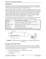
SECTION 5-WHEELCHAIR OPERATION Joystick Proportional drive control located at the front of the control provides smooth control of speed and direction. Battery Gauge Display (BGD) Located at the rear of the control provides information on the remaining charge in the batteries. At full charge, the two left segments and the farthest right segment of the bar graph are lit. As the battery becomes discharged, the farthest right segment will progressively move to the left until only the last two bars are lit; at this level the last two bars will start to flash on and off to indicate the user should charge the batteries as soon as possible. The BGD also serves as a system diagnostic device when a fault is detected by the control module. A specific number of bars (up to eight bars) will start to flash on and off to indicate the type of fault detected. A chart of the diagnostic indications is given in the Diagnostic Code Section of the electronics manual, part number 1043576. Mode and Level Indicators Two LED indicators are located on either side of the battery bar graph display. The Mode light is On (operational) with no options attached and level indicators are only operational when the optional ECU/Recliner Control or optional joysticks are utilized or the Reset switch is activated. These indicators provide information of the status of the control system and the environmental controls. The GREEN Mode indicator shows one of five control states. MODE (GREEN LED) INDICATION Drive Attendant E.C.U. or Recliner Control Stand-by Remote Drive Selection Continuously on Flashing (twice/second) Off Flashing rapidly (four/second) Slow Flashing (once/second) The RED Level indicator provides information on the control level within each mode. Its operation changes with each mode: MODE Latched Proportional Attendant Momentary ECU LEVEL INDICATOR Off Off Off Off Flashing Rapid Flashing Off On Flashing Part No 1134791 MEANING N/A N/A N/A Slowest speed has been selected. Medium speed has been selected. Fastest speed has been selected. ECU 1 and/or ECU 3 are active. ECU 2 and/or ECU 4 are active. Recliner control 57 3G Storm Series® Wheelchairs
-
 1
1 -
2
-
3
-
4
-
5
-
6
-
7
-
8
-
9
-
10
-
11
-
12
-
13
-
14
-
15
-
16
-
17
-
18
-
19
-
20
-
21
-
22
-
23
-
24
-
25
-
26
-
27
-
28
-
29
-
30
-
31
-
32
-
33
-
34
-
35
-
36
-
37
-
38
-
39
-
40
-
41
-
42
-
43
-
44
-
45
-
46
-
47
-
48
-
49
-
50
-
51
-
 52
52 -
 53
53 -
 54
54 -
 55
55 -
 56
56 -
 57
57 -
 58
58 -
 59
59 -
 60
60 -
 61
61 -
 62
62 -
63
-
64
-
65
-
66
-
67
-
68
-
69
-
70
-
71
-
72
-
73
-
74
-
75
-
76
-
77
-
78
-
79
-
80
-
81
-
82
-
83
-
84
-
85
-
86
-
87
-
88
-
89
-
90
-
91
-
92
-
93
-
94
-
95
-
96
-
97
-
98
-
99
-
100
-
101
-
102
-
103
-
104
-
105
-
106
-
107
-
108
-
109
-
110
-
111
-
112
-
113
-
114
-
115
-
116
-
117
-
118
-
119
-
120
-
121
-
122
-
123
-
124
-
125
-
126
-
127
-
128
-
129
-
130
-
131
-
132
 |
 |
