Invacare 3GAR Owners Manual 2 - Page 61
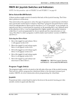
MKIV-RII Joystick Switches and Indicators
 |
View all Invacare 3GAR manuals
Add to My Manuals
Save this manual to your list of manuals |
Page 61 highlights
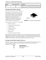
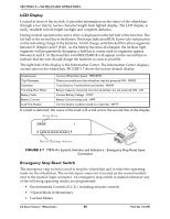
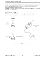
SECTION 5-WHEELCHAIR OPERATION • Pneumatic Control • Stand-by Mode • RIM Control • Remote Drive Selection Mode • Information Center Display Selection (does not require Reset activation at power up) If any of the above modes are selected, the control will require activation of the switch immediately after the power switch is turned on in order to enter the drive mode. The second line of the LCD will display - press Reset. Emergency Stop Reset Input Connector The input connector accepts a 1/8-inch diameter Phono plug. The Emergency Stop switch must be an open contact for normal driving and a closed contact to activate the Emergency Stop function. PIN TIP RING DESIGNATION RESET (EMERGENCY STOP) COMMON (B-) MKIV-RII Joystick Switches and Indicators NOTE: For this procedure, refer to FIGURE 5.8 on page 62. On/Off Switch Two position toggle is located at the back of the joystick housing. Speed Control Rotary knob is located at the back of the joystick housing. Turning the knob clockwise increases the maximum speed of the wheelchair. Joystick Proportional drive control located at the front of the joystick housing provides smooth control of speed and direction. Battery Discharge Indicator (BDI) Located at the front of the joystick housing provides information on the remaining charge in the batteries. At full charge, the BDI will be GREEN. As the battery becomes discharged, the BDI will become YELLOW (Amber), then RED and finally the BDI will flash On and Off Red. At this level, the user should charge the batteries as soon as possible. The BDI will flash On and Off YELLOW to indicate a reduced speed or power output. Part No 1134791 61 3G Storm Series® Wheelchairs
-
 1
1 -
2
-
3
-
4
-
5
-
6
-
7
-
8
-
9
-
10
-
11
-
12
-
13
-
14
-
15
-
16
-
17
-
18
-
19
-
20
-
21
-
22
-
23
-
24
-
25
-
26
-
27
-
28
-
29
-
30
-
31
-
32
-
33
-
34
-
35
-
36
-
37
-
38
-
39
-
40
-
41
-
42
-
43
-
44
-
45
-
46
-
47
-
48
-
49
-
50
-
51
-
52
-
53
-
54
-
55
-
 56
56 -
 57
57 -
 58
58 -
 59
59 -
 60
60 -
 61
61 -
 62
62 -
 63
63 -
 64
64 -
 65
65 -
 66
66 -
67
-
68
-
69
-
70
-
71
-
72
-
73
-
74
-
75
-
76
-
77
-
78
-
79
-
80
-
81
-
82
-
83
-
84
-
85
-
86
-
87
-
88
-
89
-
90
-
91
-
92
-
93
-
94
-
95
-
96
-
97
-
98
-
99
-
100
-
101
-
102
-
103
-
104
-
105
-
106
-
107
-
108
-
109
-
110
-
111
-
112
-
113
-
114
-
115
-
116
-
117
-
118
-
119
-
120
-
121
-
122
-
123
-
124
-
125
-
126
-
127
-
128
-
129
-
130
-
131
-
132
 |
 |
