Invacare 3GAR Owners Manual 2 - Page 59
MKIV-A+ Joystick Switches and Indicators
 |
View all Invacare 3GAR manuals
Add to My Manuals
Save this manual to your list of manuals |
Page 59 highlights
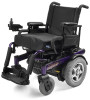
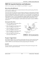
SECTION 5-WHEELCHAIR OPERATION MKIV-A+ Joystick Switches and Indicators NOTE: For this procedure, refer to FIGURE 5.6 and FIGURE 5.7 on page 60. Drive Select/On/Off Switch A three position toggle switch is located at the back of the joystick housing. The Drive Select position is momentary. This switch allows the operator to select the type of operation or performance which best suits a particular control need or situation. The Drive 1 program uses performance values which are independent of those used for the Drive 2 or 3 or 4 program. As an example, an operator may have a control need for spasticity in the morning and a very different need in the afternoon. Drive 1 can be programmed for higher speeds and quicker response while Drive 2 can be programmed for slower speeds and less responsiveness or vise versa. The other two drive programs could be indoor and outdoor versions of DRIVE 1 and Drive 2. Selecting the Drive Mode 1. Move the toggle Up and release. Drive 1 will appear on the LCD. 2. Move the toggle Up and release again. Drive 2 will appear on the LCD. 3. Move the toggle Up and release again. Drive 3 will appear on the LCD. 4. Move the toggle Up and release again. Drive 4 will appear on the LCD. 5. Move the toggle Up and release one more time to select Drive 1. LCD Program Toggle Switch Joystick To Controller On/Off Drive Select Toggle Switch FIGURE 5.6 MKIV-A+ Joystick Switches and Indicators - Drive Select/On/Off Switch Program Toggle Switch The program toggle switch is located on the left side at the rear of the joystick housing. This switch is used to program the wheelchair. Refer to the electronics manual, part number 1043576, for more information about programming the wheelchair. Joystick Proportional drive control knob located at the front of the joystick housing provides smooth control of speed and direction. Part No 1134791 59 3G Storm Series® Wheelchairs
-
 1
1 -
2
-
3
-
4
-
5
-
6
-
7
-
8
-
9
-
10
-
11
-
12
-
13
-
14
-
15
-
16
-
17
-
18
-
19
-
20
-
21
-
22
-
23
-
24
-
25
-
26
-
27
-
28
-
29
-
30
-
31
-
32
-
33
-
34
-
35
-
36
-
37
-
38
-
39
-
40
-
41
-
42
-
43
-
44
-
45
-
46
-
47
-
48
-
49
-
50
-
51
-
52
-
53
-
 54
54 -
 55
55 -
 56
56 -
 57
57 -
 58
58 -
 59
59 -
 60
60 -
 61
61 -
 62
62 -
 63
63 -
 64
64 -
65
-
66
-
67
-
68
-
69
-
70
-
71
-
72
-
73
-
74
-
75
-
76
-
77
-
78
-
79
-
80
-
81
-
82
-
83
-
84
-
85
-
86
-
87
-
88
-
89
-
90
-
91
-
92
-
93
-
94
-
95
-
96
-
97
-
98
-
99
-
100
-
101
-
102
-
103
-
104
-
105
-
106
-
107
-
108
-
109
-
110
-
111
-
112
-
113
-
114
-
115
-
116
-
117
-
118
-
119
-
120
-
121
-
122
-
123
-
124
-
125
-
126
-
127
-
128
-
129
-
130
-
131
-
132
 |
 |
