Invacare 3GAR Owners Manual 2 - Page 63
Front Riggings
 |
View all Invacare 3GAR manuals
Add to My Manuals
Save this manual to your list of manuals |
Page 63 highlights
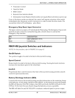
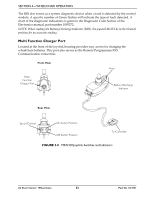
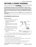
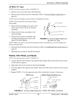
SECTION 6-FRONT RIGGINGS SECTION 6-FRONT RIGGINGS ƽ WARNING After ANY adjustments, repair or service and BEFORE use, make sure that all attaching hardware is tightened securely - otherwise injury or damage may result. While the wheelchair is moving, minimum ground clearance for the front rigging is three inches. If the wheelchair is not moving, the front rigging MUST maintain a minimum of one inch ground clearance - otherwise personal injury and damage may result. For the following procedures, make sure the ON/OFF switch on the joystick is in the OFF position. Installing/Removing Footrests 70°/Taper Pin Style NOTE: For this procedure, refer to FIGURE 6.1. 1. Turn the footrest to the side (open footplate is perpendicular to wheelchair). Footrest Release Lever 2. Install the hinge plates on the footrest onto the hinge pins on the wheelchair frame. 3. Push the footrest towards the inside of the wheelchair until it locks into place. Hinge Pins Hinge Plate NOTE: The footplate will be on the inside of the wheelchair when locked in place. Footrest 4. Repeat STEPS 1-3 for other footrest assembly. FIGURE 6.1 Installing/Removing Footrests 70°/Taper Pin Style 5. To remove the footrest, push the footrest release lever inward, rotate footrest outward. 6. Adjust footrest height if desired. Refer to Footrest Height Adjustment on page 64. 60°, 70°, MFX, Taper and 90° NOTE: For this procedure, refer to FIGURE 6.2 on page 64. 1. Turn the footrest to the side (open footplate is perpendicular to wheelchair itself). 2. Insert footrest mounting pin into mounting tube. 3. Push the footrest towards the inside of the wheelchair until it locks into place. NOTE: The footplate will be on the inside of the wheelchair when locked in place. 4. Repeat STEPS 1- 3 for the other footrest assembly. Part No 1134791 63 3G Storm Series® Wheelchairs
-
 1
1 -
2
-
3
-
4
-
5
-
6
-
7
-
8
-
9
-
10
-
11
-
12
-
13
-
14
-
15
-
16
-
17
-
18
-
19
-
20
-
21
-
22
-
23
-
24
-
25
-
26
-
27
-
28
-
29
-
30
-
31
-
32
-
33
-
34
-
35
-
36
-
37
-
38
-
39
-
40
-
41
-
42
-
43
-
44
-
45
-
46
-
47
-
48
-
49
-
50
-
51
-
52
-
53
-
54
-
55
-
56
-
57
-
 58
58 -
 59
59 -
 60
60 -
 61
61 -
 62
62 -
 63
63 -
 64
64 -
 65
65 -
 66
66 -
 67
67 -
 68
68 -
69
-
70
-
71
-
72
-
73
-
74
-
75
-
76
-
77
-
78
-
79
-
80
-
81
-
82
-
83
-
84
-
85
-
86
-
87
-
88
-
89
-
90
-
91
-
92
-
93
-
94
-
95
-
96
-
97
-
98
-
99
-
100
-
101
-
102
-
103
-
104
-
105
-
106
-
107
-
108
-
109
-
110
-
111
-
112
-
113
-
114
-
115
-
116
-
117
-
118
-
119
-
120
-
121
-
122
-
123
-
124
-
125
-
126
-
127
-
128
-
129
-
130
-
131
-
132
 |
 |
