Invacare 3GAR Owners Manual 2 - Page 67
Installing Adjustable Angle Flip-up Footplate Hinge
 |
View all Invacare 3GAR manuals
Add to My Manuals
Save this manual to your list of manuals |
Page 67 highlights
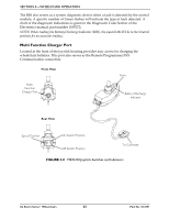
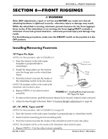
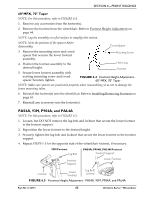
SECTION 6-FRONT RIGGINGS Wheelchairs with 2G Tarsys Seating Systems NOTE: For this procedure, refer to FIGURE 6.7. 1. Remove the two mounting screws, spacers and locknuts that secure the telescoping front rigging support to the seat frame. 2. Perform one of the following: • Slide existing telescoping front rigging support to one of three depth positions. Seat Frame Mounting Screw • Remove existing telescoping front rigging. Spacers 3. Secure telescoping front rigging at desired depth with existing two mounting screws, spacers, and locknuts. Securely tighten. Locknut Telescoping Front Tube FIGURE 6.7 Adjusting/Replacing Telescoping Front Rigging Support NOTE: The two telescoping front rigging supports can be positioned at different depths depending on the need of the user. Installing Adjustable Angle Flip-up Footplate Hinge NOTE: For this procedure, refer to FIGURE 6.8. 1. Position footplate hinge on the footrest support tube at the desired height. 2. Position mounting screw, washers, spacer, and locknut on the footrest support as shown in FIGURE 6.8. 3. Flip the footplate hinge to the Up position. NOTE: The footplate hinge will fall to the Down position. 4. Tighten the mounting screw, washer, and locknut that secure the footplate hinge to the footrest support until the footplate hinge remains in the Up position. 5. Check the up and down motion of the footplate hinge to make sure the user of the wheelchair can operate the footplates easily. NOTE: If footplate's motion is too tight, loosen the mounting screw and locknut approximately 1/4-turn counter clockwise. NOTE: If the footplate's motion is too loose, tighten mounting screw and locknut approximately 1/4-turn clockwise. 6. Adjust footplate. Refer to Installing Adjustable Angle Flip-up Footplate Hinge on page 67. Footplate Hinge Locknut Spacer Mounting Screw Washers Footrest Support FIGURE 6.8 Installing Adjustable Angle Flip-up Footplate Hinge Part No 1134791 67 3G Storm Series® Wheelchairs
-
 1
1 -
2
-
3
-
4
-
5
-
6
-
7
-
8
-
9
-
10
-
11
-
12
-
13
-
14
-
15
-
16
-
17
-
18
-
19
-
20
-
21
-
22
-
23
-
24
-
25
-
26
-
27
-
28
-
29
-
30
-
31
-
32
-
33
-
34
-
35
-
36
-
37
-
38
-
39
-
40
-
41
-
42
-
43
-
44
-
45
-
46
-
47
-
48
-
49
-
50
-
51
-
52
-
53
-
54
-
55
-
56
-
57
-
58
-
59
-
60
-
61
-
 62
62 -
 63
63 -
 64
64 -
 65
65 -
 66
66 -
 67
67 -
 68
68 -
 69
69 -
 70
70 -
 71
71 -
 72
72 -
73
-
74
-
75
-
76
-
77
-
78
-
79
-
80
-
81
-
82
-
83
-
84
-
85
-
86
-
87
-
88
-
89
-
90
-
91
-
92
-
93
-
94
-
95
-
96
-
97
-
98
-
99
-
100
-
101
-
102
-
103
-
104
-
105
-
106
-
107
-
108
-
109
-
110
-
111
-
112
-
113
-
114
-
115
-
116
-
117
-
118
-
119
-
120
-
121
-
122
-
123
-
124
-
125
-
126
-
127
-
128
-
129
-
130
-
131
-
132
 |
 |
