Invacare 3GAR Owners Manual 2 - Page 58
Emergency Stop Reset Switch, Emergency Stop Reset Input Connector
 |
View all Invacare 3GAR manuals
Add to My Manuals
Save this manual to your list of manuals |
Page 58 highlights
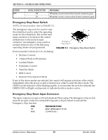
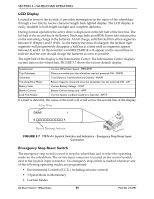
SECTION 5-WHEELCHAIR OPERATION MODE RIM LEVEL INDICATOR Off On MEANING Wheelchair moves forward when forward command is given. Wheelchair moves in reverse when forward command is given. Emergency Stop Reset Switch NOTE: For this procedure, refer to FIGURE 5.5. The emergency stop switch is used to stop the wheelchair and to select the operating mode for the wheelchair. The switch reset input connector is located on the control module next to the joystick input connector. An emergency stop switch is needed whenever any of the following operating modes are programmed. Emergency Stop Switch FIGURE 5.5 Emergency Stop Reset Switch Environmental Controls (E.C.U.) including: • Recliner Controls • 3 Speed Mode in Momentary • Latched Modes • Pneumatic Control • Stand-by Mode • RIM Control • Remote Drive Selection Mode If any of the above modes are selected, the control will require activation of the switch immediately after the power switch is turned on in order to enter the drive mode. The GREEN mode indicator will be flashing rapidly. A second after the switch is released, the GREEN LED will light continuously to indicate the drive mode is active. Emergency Stop Reset Input Connector The input connector accepts a 1/8-inch diameter Phono plug. The Emergency Stop switch must be an open contact for normal driving and a closed contact to activate the Emergency Stop function. PIN DESIGNATION TIP RING RESET (EMERGENCY STOP) COMMON (B-) 3G Storm Series® Wheelchairs 58 Part No 1134791
-
 1
1 -
2
-
3
-
4
-
5
-
6
-
7
-
8
-
9
-
10
-
11
-
12
-
13
-
14
-
15
-
16
-
17
-
18
-
19
-
20
-
21
-
22
-
23
-
24
-
25
-
26
-
27
-
28
-
29
-
30
-
31
-
32
-
33
-
34
-
35
-
36
-
37
-
38
-
39
-
40
-
41
-
42
-
43
-
44
-
45
-
46
-
47
-
48
-
49
-
50
-
51
-
52
-
 53
53 -
 54
54 -
 55
55 -
 56
56 -
 57
57 -
 58
58 -
 59
59 -
 60
60 -
 61
61 -
 62
62 -
 63
63 -
64
-
65
-
66
-
67
-
68
-
69
-
70
-
71
-
72
-
73
-
74
-
75
-
76
-
77
-
78
-
79
-
80
-
81
-
82
-
83
-
84
-
85
-
86
-
87
-
88
-
89
-
90
-
91
-
92
-
93
-
94
-
95
-
96
-
97
-
98
-
99
-
100
-
101
-
102
-
103
-
104
-
105
-
106
-
107
-
108
-
109
-
110
-
111
-
112
-
113
-
114
-
115
-
116
-
117
-
118
-
119
-
120
-
121
-
122
-
123
-
124
-
125
-
126
-
127
-
128
-
129
-
130
-
131
-
132
 |
 |
