Netgear GSM7248v1 GSM7224 Administration manual - Page 23
Configuring for Out-Of-Band Connectivity, Ctrl-Z, save config, show network, IP Address, Subnet
 |
View all Netgear GSM7248v1 manuals
Add to My Manuals
Save this manual to your list of manuals |
Page 23 highlights
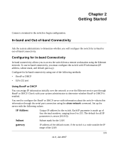
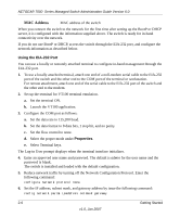
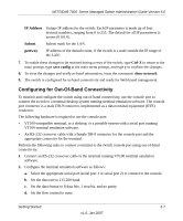
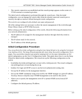
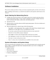
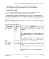
NETGEAR 7000 Series Managed Switch Administration Guide Version 6.0 IP Address Unique IP address for the switch. Each IP parameter is made up of four decimal numbers, ranging from 0 to 255. The default for all IP parameters is zeroes (0.0.0.0). Subnet gateway Subnet mask for the LAN. IP address of the default router, if the switch is a node outside the IP range of the LAN. 7. To enable these changes to be retained during a reset of the switch, type Ctrl-Z to return to the main prompt, type save config at the main menu prompt, and type y to confirm the changes. 8. To view the changes and verify in-band information, issue the command: show network. 9. The switch is configured for in-band connectivity and ready for Web-based management. Configuring for Out-Of-Band Connectivity To monitor and configure the switch using out-of-band connectivity, use the console port to connect the switch to a terminal desktop system running terminal emulation software. The console port connector is a male DB-9 connector, implemented as a data terminal equipment (DTE) connector. The following hardware is required to use the console port: • VT100-compatible terminal, or a desktop, or a portable system with a serial port running VT100 terminal emulation software. • An RS-232 crossover cable with a female DB-9 connector for the console port and the appropriate connector for the terminal. Perform the following tasks to connect a terminal to the switch console port using out-of-band connectivity: 1. Connect an RS-232 crossover cable to the terminal running VT100 terminal emulation software. 2. Configure the terminal emulation software as follows: a. Select the appropriate serial port (serial port 1 or serial port 2) to connect to the console. b. Set the data rate to 115,200 baud. c. Set the data format to 8 data bits, 1 stop bit, and no parity. d. Set the flow control to none. Getting Started 2-7 v1.0, Jan 2007
-
 1
1 -
2
-
3
-
4
-
5
-
6
-
7
-
8
-
9
-
10
-
11
-
12
-
13
-
14
-
15
-
16
-
17
-
 18
18 -
 19
19 -
 20
20 -
 21
21 -
 22
22 -
 23
23 -
 24
24 -
 25
25 -
 26
26 -
 27
27 -
 28
28 -
29
-
30
-
31
-
32
-
33
-
34
-
35
-
36
-
37
-
38
-
39
-
40
-
41
-
42
-
43
-
44
-
45
-
46
-
47
-
48
-
49
-
50
-
51
-
52
-
53
-
54
-
55
-
56
-
57
-
58
-
59
-
60
-
61
-
62
-
63
-
64
-
65
-
66
-
67
-
68
-
69
-
70
-
71
-
72
-
73
-
74
-
75
-
76
-
77
-
78
-
79
-
80
-
81
-
82
-
83
-
84
-
85
-
86
-
87
-
88
-
89
-
90
-
91
-
92
-
93
-
94
-
95
-
96
-
97
-
98
-
99
-
100
-
101
-
102
-
103
-
104
-
105
-
106
-
107
-
108
-
109
-
110
-
111
-
112
-
113
-
114
-
115
-
116
-
117
-
118
-
119
-
120
-
121
-
122
-
123
-
124
-
125
-
126
-
127
-
128
-
129
-
130
-
131
-
132
-
133
-
134
-
135
-
136
-
137
-
138
-
139
-
140
-
141
-
142
-
143
-
144
-
145
-
146
-
147
-
148
 |
 |
