Netgear GSM7248v1 GSM7224 Administration manual - Page 71
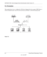
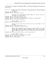
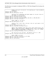
The following is an example of configuring VRRP on a 7000 Series Managed Switch acting as
 |
View all Netgear GSM7248v1 manuals
Add to My Manuals
Save this manual to your list of manuals |
Page 71 highlights
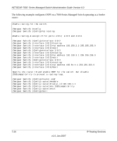
NETGEAR 7000 Series Managed Switch Administration Guide Version 6.0 The following is an example of configuring VRRP on a 7000 Series Managed Switch acting as the master router: Enable routing for the switch. IP forwarding will then be enabled by default. (Netgear Switch) #config (Netgear Switch) (Config)#ip routing Configure the IP addresses and subnet masks for the port that will particpate in the protocol. (Netgear Switch) (Config)#interface 1/0/2 (Netgear Switch) (Interface 1/0/2)#routing (Netgear Switch) (Interface 1/0/2)#ip address 192.150.2.1 255.255.255.0 (Netgear Switch) (Interface 1/0/2)#exit Enable VRRP for the switch. (Netgear Switch) (Config)#ip vrrp Assign virtual router IDs to the port that will particpate in the protocol. (Netgear Switch) (Config)#interface 1/0/2 (Netgear Switch) (Interface 1/0/2)#ip vrrp 20 Specify the IP address that the virtual router function will recognize. Note that the virtual IP address on port 1/0/2 is the same as the port's actual IP address, therefore this router will always be the VRRP master when it is active. And the priority default is 255. (Netgear Switch) (Interface 1/0/2)#ip vrrp 20 ip 192.150.2.1 Enable VRRP on the port. (Netgear Switch) (Interface 1/0/2)#ip vrrp 20 mode (Netgear Switch) (Interface 1/0/2)#exit (Netgear Switch) (Config)#exit Virtual Router Redundancy Protocol 8-3 v1.0, Jan 2007
-
 1
1 -
2
-
3
-
4
-
5
-
6
-
7
-
8
-
9
-
10
-
11
-
12
-
13
-
14
-
15
-
16
-
17
-
18
-
19
-
20
-
21
-
22
-
23
-
24
-
25
-
26
-
27
-
28
-
29
-
30
-
31
-
32
-
33
-
34
-
35
-
36
-
37
-
38
-
39
-
40
-
41
-
42
-
43
-
44
-
45
-
46
-
47
-
48
-
49
-
50
-
51
-
52
-
53
-
54
-
55
-
56
-
57
-
58
-
59
-
60
-
61
-
62
-
63
-
64
-
65
-
 66
66 -
 67
67 -
 68
68 -
 69
69 -
 70
70 -
 71
71 -
 72
72 -
 73
73 -
 74
74 -
 75
75 -
 76
76 -
77
-
78
-
79
-
80
-
81
-
82
-
83
-
84
-
85
-
86
-
87
-
88
-
89
-
90
-
91
-
92
-
93
-
94
-
95
-
96
-
97
-
98
-
99
-
100
-
101
-
102
-
103
-
104
-
105
-
106
-
107
-
108
-
109
-
110
-
111
-
112
-
113
-
114
-
115
-
116
-
117
-
118
-
119
-
120
-
121
-
122
-
123
-
124
-
125
-
126
-
127
-
128
-
129
-
130
-
131
-
132
-
133
-
134
-
135
-
136
-
137
-
138
-
139
-
140
-
141
-
142
-
143
-
144
-
145
-
146
-
147
-
148
 |
 |
