Netgear GSM7248v1 GSM7224 Administration manual - Page 51
VLAN Routing Configuration, CLI Examples, show ip vlan
 |
View all Netgear GSM7248v1 manuals
Add to My Manuals
Save this manual to your list of manuals |
Page 51 highlights
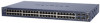
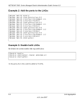
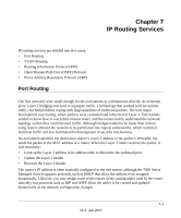
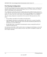
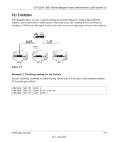
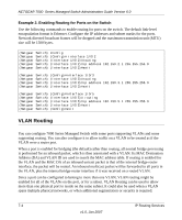
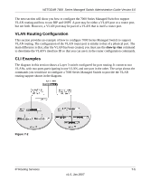
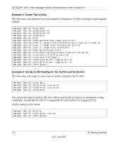
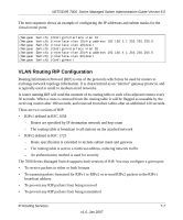
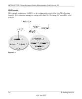
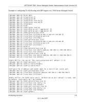
NETGEAR 7000 Series Managed Switch Administration Guide Version 6.0 The next section will show you how to configure the 7000 Series Managed Switch to support VLAN routing and how to use RIP and OSPF. A port may be either a VLAN port or a router port, but not both. However, a VLAN port may be part of a VLAN that is itself a router port. VLAN Routing Configuration This section provides an example of how to configure 7000 Series Managed Switch to support VLAN routing. The configuration of the VLAN router port is similar to that of a physical port. The main difference is that, after the VLAN has been created, you must use the show ip vlan command to determine the VLAN's interface ID so that you can use it in the router configuration commands. CLI Examples The diagram in this section shows a Layer 3 switch configured for port routing. It connects two VLANs, with two ports participating in one VLAN, and one port in the other. The script shows the commands you would use to configure a 7000 Series Managed Switch to provide the VLAN routing support shown in the diagram. Figure 7-2 IP Routing Services 7-5 v1.0, Jan 2007
-
 1
1 -
2
-
3
-
4
-
5
-
6
-
7
-
8
-
9
-
10
-
11
-
12
-
13
-
14
-
15
-
16
-
17
-
18
-
19
-
20
-
21
-
22
-
23
-
24
-
25
-
26
-
27
-
28
-
29
-
30
-
31
-
32
-
33
-
34
-
35
-
36
-
37
-
38
-
39
-
40
-
41
-
42
-
43
-
44
-
45
-
 46
46 -
 47
47 -
 48
48 -
 49
49 -
 50
50 -
 51
51 -
 52
52 -
 53
53 -
 54
54 -
 55
55 -
 56
56 -
57
-
58
-
59
-
60
-
61
-
62
-
63
-
64
-
65
-
66
-
67
-
68
-
69
-
70
-
71
-
72
-
73
-
74
-
75
-
76
-
77
-
78
-
79
-
80
-
81
-
82
-
83
-
84
-
85
-
86
-
87
-
88
-
89
-
90
-
91
-
92
-
93
-
94
-
95
-
96
-
97
-
98
-
99
-
100
-
101
-
102
-
103
-
104
-
105
-
106
-
107
-
108
-
109
-
110
-
111
-
112
-
113
-
114
-
115
-
116
-
117
-
118
-
119
-
120
-
121
-
122
-
123
-
124
-
125
-
126
-
127
-
128
-
129
-
130
-
131
-
132
-
133
-
134
-
135
-
136
-
137
-
138
-
139
-
140
-
141
-
142
-
143
-
144
-
145
-
146
-
147
-
148
 |
 |
