Netgear GSM7248v1 GSM7224 Administration manual - Page 52
Example 1: Create Two VLANs, Example 2: Set Up VLAN Routing for the VLANs and the Switch.
 |
View all Netgear GSM7248v1 manuals
Add to My Manuals
Save this manual to your list of manuals |
Page 52 highlights
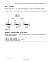
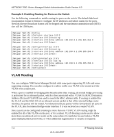
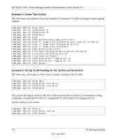
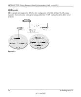
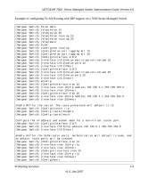
NETGEAR 7000 Series Managed Switch Administration Guide Version 6.0 Example 1: Create Two VLANs The following code sequence shows an example of creating two VLANs with egress frame tagging enabled. (Netgear Switch) #vlan data (Netgear Switch) (Vlan)#vlan 10 (Netgear Switch) (Vlan)#vlan 20 (Netgear Switch) (Vlan)#exit (Netgear Switch) #conf (Netgear Switch) (Config)#interface range 1/0/1-1/0/2 (Netgear Switch) (conf-if-range-1/0/1-1/0/2)#vlan participation include 10 (Netgear Switch) (conf-if-range-1/0/1-1/0/2)#vlan pvid 10 (Netgear Switch) (conf-if-range-1/0/1-1/0/2)#exit (Netgear Switch) (Config)#interface 1/0/3 (Netgear Switch) (Interface 1/0/3)#vlan participation include 20 (Netgear Switch) (Interface 1/0/3)#vlan pvid 20 (Netgear Switch) (Interface 1/0/3)#exit (Netgear Switch) (Config)#vlan port tagging all 10 (Netgear Switch) (Config)#vlan port tagging all 20 (Netgear Switch) (Config)#exit Example 2: Set Up VLAN Routing for the VLANs and the Switch. The following code sequence shows how to enable routing for the VLANs: (Netgear Switch) #vlan data (Netgear Switch) (Vlan)#vlan routing 10 (Netgear Switch) (Vlan)#vlan routing 20 (Netgear Switch) (Vlan)#exit This returns the logical interface IDs that will be used instead of slot/port in subsequent routing commands. Assume that VLAN 10 is assigned ID 3/1 and VLAN 20 is assigned ID 3/2. Enable routing for the switch: (Netgear Switch) #config (Netgear Switch) (Config)#ip routing (Netgear Switch) (Config)#exit 7-6 IP Routing Services v1.0, Jan 2007
-
 1
1 -
2
-
3
-
4
-
5
-
6
-
7
-
8
-
9
-
10
-
11
-
12
-
13
-
14
-
15
-
16
-
17
-
18
-
19
-
20
-
21
-
22
-
23
-
24
-
25
-
26
-
27
-
28
-
29
-
30
-
31
-
32
-
33
-
34
-
35
-
36
-
37
-
38
-
39
-
40
-
41
-
42
-
43
-
44
-
45
-
46
-
 47
47 -
 48
48 -
 49
49 -
 50
50 -
 51
51 -
 52
52 -
 53
53 -
 54
54 -
 55
55 -
 56
56 -
 57
57 -
58
-
59
-
60
-
61
-
62
-
63
-
64
-
65
-
66
-
67
-
68
-
69
-
70
-
71
-
72
-
73
-
74
-
75
-
76
-
77
-
78
-
79
-
80
-
81
-
82
-
83
-
84
-
85
-
86
-
87
-
88
-
89
-
90
-
91
-
92
-
93
-
94
-
95
-
96
-
97
-
98
-
99
-
100
-
101
-
102
-
103
-
104
-
105
-
106
-
107
-
108
-
109
-
110
-
111
-
112
-
113
-
114
-
115
-
116
-
117
-
118
-
119
-
120
-
121
-
122
-
123
-
124
-
125
-
126
-
127
-
128
-
129
-
130
-
131
-
132
-
133
-
134
-
135
-
136
-
137
-
138
-
139
-
140
-
141
-
142
-
143
-
144
-
145
-
146
-
147
-
148
 |
 |
