Panasonic WVCU360C WVCU360C User Guide
Panasonic WVCU360C - SYSTEM CONTROLLER Manual
 |
UPC - 791871503454
View all Panasonic WVCU360C manuals
Add to My Manuals
Save this manual to your list of manuals |
Panasonic WVCU360C manual content summary:
- Panasonic WVCU360C | WVCU360C User Guide - Page 1
ENGLISH System Controller Operating Instructions Model No. WV-CU360C OPERATE LOGIN ALARM SHIFT ALM RESET VCRALMCRAEMCALL SETUP CAM System Controller WV-CU C UP R FRANÇAIS Before attempting to connect or operate this product, please read these instructions carefully and save this manual - Panasonic WVCU360C | WVCU360C User Guide - Page 2
is intended to alert the user to the presence of important operating and maintenance (servicing) instructions in the literature accompanying the appliance , if not installed and used in accordance with the instruction manual, may cause harmful interference to radio communications. Operation of - Panasonic WVCU360C | WVCU360C User Guide - Page 3
. Install in accordance with the manufacturer's instructions. 8) Do not use near any heat When a cart is used, use caution when moving the cart/apparatus combination to avoid injury from tip of time. 14) Refer all servicing to qualified service personnel. Servicing is required when the apparatus has - Panasonic WVCU360C | WVCU360C User Guide - Page 4
PS •Data 22 s Basic Operating Flow 22 s Login/Logout 23 s System Unit Selection 24 s Monitor Selection 25 s Camera Selection 25 s Camera Control 26 s Data Multiplex Unit Control 28 s Video Multiplexer Control 29 s Digital Disk Recorder Control 31 s Alarm Operation 34 REMOTE SETUP of UNITS - Panasonic WVCU360C | WVCU360C User Guide - Page 5
PREFACE The System Controller WV-CU360C is designed for setup and operation of cameras and other system units installed in a surveillance system. The controller is compatible with the Panasonic Security Data (PS •Data) protocol by default, but DIP switches are provided to select the conventional - Panasonic WVCU360C | WVCU360C User Guide - Page 6
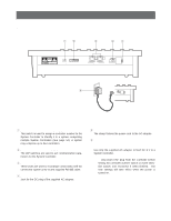
to the AC adapter. y AC Adapter Caution: Use only the supplied AC adapter to feed DC 9 V to a System Controller. Note: Disconnect the plug from the controller before setting the controller number switch or mode selection switch, and reconnect it when finished. The new settings will take effect when - Panasonic WVCU360C | WVCU360C User Guide - Page 7
SEQ SEQ DEF OFF DEF ON CLEAR F2 OSD MONITOR (ESC) CAM FUNC LOCK OSD SERVICE SHIFT BLK EXIT 360 BUSY PROHIBITED System Controller WV-CU C For Matrix Switcher (System 850) CAMERA SITE CONTROL IRIS CLOSE OPEN IRIS RESET UP PROGRAM PRESET FOCUS NEAR FAR AUTO FOCUS L R CALL - Panasonic WVCU360C | WVCU360C User Guide - Page 8
. 23 WJ-FS616 WJ-SX350 (Ver. 6.00 or later) WJ-SX350 (Ver. 1.xx) 78 78 78 901 #1 CONTROLLER No. 901 #1 CONTROLLER No. 901 #1 CONTROLLER No. 23 23 23 System 850 WJ-SX850 78 901 #1 CONTROLLER No. 23 MODE DIP SW OFF ON 1 234 5678 MODE OFF ON 1 234 5678 MODE OFF ON 1 234 5678 MODE - Panasonic WVCU360C | WVCU360C User Guide - Page 9
Panasonic Security Data (PS•Data) Systems 9 - Panasonic WVCU360C | WVCU360C User Guide - Page 10
& THEIR FUNCTIONS s Front View (Template for PS•Data) qwe rt yu i OPERATE LOGIN ALARM MONITOR UNIT CAMERA 360 BUSY PROHIBITED System Controller WV-CU C !8 !9 SETUP PROGRAM CAM SETUP IRIS @0 SHIFT FUNCTION CAM FUNCTION @5 ALM RESET ALM SUSPEND AUTO CLOSE OPEN IRIS RESET - Panasonic WVCU360C | WVCU360C User Guide - Page 11
button together with the CAM/SET button for approximately 2 seconds will log out from the system. !8 Programme/Camera Setup/Camera Function button (PROGRAM/CAM SETUP/CAM FUNCTION) Programmes camera patrol learning and preset position functions. Pressing this button for 2 seconds or more will open - Panasonic WVCU360C | WVCU360C User Guide - Page 12
in the shift mode will turn on the AUX 2 function controlling accessories connected to the cameras or the system. The LED next to the button is lit while the in the shift mode will move the camera sequence one step forward from the step previously paused while a system unit provided with SEQ PAUSE - Panasonic WVCU360C | WVCU360C User Guide - Page 13
instructions. s System Connections q Connection Example Example 1 shows 8 cameras connected to 2 Data Multiplex Units (WJ-MP204C), to a Video Multiplexer (e.g., WJ-FS316) and a Digital Disk Recorder (e.g., WJ-HD100). The WV-CU360C controls these system Line Termination OFF Panasonic Security Data - Panasonic WVCU360C | WVCU360C User Guide - Page 14
1 - 2 WJ-MP204C ← WV-CU360C GND 1 Controller end TX(B) 2 1 3 WJ-MP204C ← WV-CU360C TX(A) 3 4 WJ-MP204C → WV-CU360C RX(B) 4 6 5 WJ-MP204C → WV-CU360C RX(A) 5 6 6 - GND 6 TX (B) TX (A) RX (B) RX (A) • Basic Connection Data Multiplex Unit WJ-MP204C System Controller WV-CU360C 14 DATA - Panasonic WVCU360C | WVCU360C User Guide - Page 15
• Daisy Chain Connection Video Multiplexer WJ-FS309 (WJ-FS316) Data Multiplex Unit WJ-MP204C System Controller WV-CU360C DATA Termination: ON DATA Termination: OFF Branch Cable RS-485 Cable DATA Termination: ON RS-485 Cable s DIP Switch Setting (PS •Data) An 8-bit DIP - Panasonic WVCU360C | WVCU360C User Guide - Page 16
Setting (PS •Data) A 10-position rotary switches provided on the rear for specifying the unit number of the WV-CU360C controller in a PS •Data system. 1. Remove the DC plug from the rear of the controller. 2. Use a screw driver to rotate the switch so that the arrow comes to the number you wish. 901 - Panasonic WVCU360C | WVCU360C User Guide - Page 17
SETUP PROCEDURES (PS•Data) To display the setup menus for the WV-CU360C System Controller on the LED display, set the MODE switch and power up the controller as described below. s Prior to Setup Do the following before entering the setup mode. 1. Confirm that all necessary connections and - Panasonic WVCU360C | WVCU360C User Guide - Page 18
Move Joystick up and down to select L R DOWN UP L R Parity Parity Check Wait Wait Time (ms) Controller Unit Group System Unit Group Unit A Number Unit B Number Unit Assignment to Button A Unit Assignment to Button B User Password Super User Password Administrator Password User User - Panasonic WVCU360C | WVCU360C User Guide - Page 19
button twice. 2. Select a parameter entering a bracket-enclosed number, e.g., (3), moving the joystick right and left, or pressing the [+] and [-] button. The condition. q Controller Unit-Group Address [CU-gr] appears on the Setup menu, but leave the default as it is. q System Unit-Group Address - Panasonic WVCU360C | WVCU360C User Guide - Page 20
system with many units connected and could confuse operators. A frequently used system to go back to the previous menu. q User Password Certification In this menu, password certification in -oF]. 2. Select On or Off with the joystick controller. The default setting is On. on: Password certification - Panasonic WVCU360C | WVCU360C User Guide - Page 21
cleaning function causes cleaning of the builtin slip rings that conduct electric signals while moving the pan/tilt head. All combination cameras connected to the system are cleaned in the order specified here. Picture viewing is disabled during the cleaning process. 1. Display [CLEAn] and press - Panasonic WVCU360C | WVCU360C User Guide - Page 22
PROCEDURES (PS•Data) s Basic Operating Flow The operation starts with a log-in procedure. It proceeds to system unit selection, monitor selection and camera selection. Alarm operations for the system such as alarm reset, suspension may be implemented. The operation ends with a log-out procedure - Panasonic WVCU360C | WVCU360C User Guide - Page 23
system administrator. 1. Insert the DC plug into the DC 9 V IN jack and connect the AC adapter to an AC outlet. 2. The controller number, software versions and [LogIn /SET button. 6. If password entry for user authorization has been successful, the LOGIN indicator lights up. The unit assigned to the - Panasonic WVCU360C | WVCU360C User Guide - Page 24
such as Data Multiplex Unit are connected to the System Controller and the UNIT A or UNIT B button is pressed, the camera number on the controller's LED display will not agree with the camera picture on the monitor. In this case, select the monitor and camera as described on the next page. MON CAM - Panasonic WVCU360C | WVCU360C User Guide - Page 25
. The selected camera number appears in the camera section of the LED display. The monitor is now ready for control from the system controller. Notes: refer to the Operating Instructions for the system unit concerned. MON CAM ESC LOGOUT SET Note: [--] appears in the camera section of the LED - Panasonic WVCU360C | WVCU360C User Guide - Page 26
. The operating procedures on the following pages assume that you have selected a system unit and a monitor. q Pan/Tilt Control Proceed as follows to control a combination camera or an ordinary camera mounted on a pan/tilt head. 1. Move the pan/tilt head in the desired direction with the joystick - Panasonic WVCU360C | WVCU360C User Guide - Page 27
available for controlling combination cameras. For more details, refer to the Operating Instructions included with the camera. Function Key Move to HOME [8] + [9] + [CAM FUNC] B/W or C/L B/W On* [9] + [0] + [CAM FUNC] B/W Off* [9] + [1] + [CAM FUNC] B/W AUTO* [9] + [2] + [CAM FUNC] CAMERA - Panasonic WVCU360C | WVCU360C User Guide - Page 28
the WJ-MP204C. For further details, refer to the manual included with the Data Multiplex Unit. Unit Address of WJ-MP204C 1 2 3 4 Camera Number 1, 2, 3, 4 5, 6, 7, 8 9, 10, 11, 12 13, 14, 15, 16 When more than one controller is connected in the system, remember settings are needed for the MODE DIP - Panasonic WVCU360C | WVCU360C User Guide - Page 29
equipped in a Video Multiplexer are remotely controlled from the System Controller. For more information, refer to the manual included with the Video Multiplexer. The operating procedures on the following pages assume that you have selected a system unit and a monitor. q Multiscreen Selection - Panasonic WVCU360C | WVCU360C User Guide - Page 30
Video Multiplexer. Set PLAYBACK AUTO to OFF in the setup when you wish manual operations as described above. q Sequence Control A preset sequence is displayed on the selected spot or multiscreen monitor. The paused picture can be moved by one step to the previous or next frame. 1. Press the SEQUENCE - Panasonic WVCU360C | WVCU360C User Guide - Page 31
controlled from the System Controller using shortcuts assigned to numeric buttons. For more information, refer to the manual included with the Digital Disk Recorder. The operating procedures on the following pages assume that you have selected a system JJooggDDiaial l WV-CU360C HolHdolddodwownn 2 - Panasonic WVCU360C | WVCU360C User Guide - Page 32
WV-CU360C 13 30 31 SETUP Note FUNCTION SETUP FUNCTION SETUP OFF, INT or EXT selectable FUNCTION SETUP FUNCTION q WJ-HD500A Shortcuts The shortcuts listed below are available for controlling a digital disk recorder. For more details, refer to the Operating Instructions both Manual Recording - Panasonic WVCU360C | WVCU360C User Guide - Page 33
Backward Search in Window Forward Search in Window Increment Parameter in Window Decrement Parameter in Window Search Window Display Selection 33 Controller Operation SETUP Note SHIFT FUNCTION SETUP SHIFT SHIFT SHIFT SHIFT FUNCTION ALM RESET ALM RECALL SETUP FUNCTION SETUP FUNCTION SETUP - Panasonic WVCU360C | WVCU360C User Guide - Page 34
s Alarm Operation When the WV-CU360C receives an alarm signal from a system unit, the alarm indicator on the controller blinks. The alarm indicator changes from blinking to steady light when the alarm is automatically reset. The camera number [---] appears in the camera section of the LED display - Panasonic WVCU360C | WVCU360C User Guide - Page 35
CAMERAS You can set up the system unit and the camera with the setup menu by this controller. You can use the controller to set up system units and cameras Instructions included with the individual units. s System Unit Setup 1. Select the desired system SPECIAL1 CAMERA RS485 SET UP 3. Move the - Panasonic WVCU360C | WVCU360C User Guide - Page 36
on the camera. If camera setup is started using the System Controller, all future operations for setup must be performed using the same controller. • For further information, refer to the Operating Instructions for the selected camera. Keys used for camera setup s Camera Patrol Learning There - Panasonic WVCU360C | WVCU360C User Guide - Page 37
camera positions. One is to use the camera setup menu of the combination camera and the other is to operate the System Controller as follows. 1. Select the desired system unit, monitor and camera. 2. Move the camera depending on the camera type. Refer to the manual included with the camera. 3. Type - Panasonic WVCU360C | WVCU360C User Guide - Page 38
For WJ-FS616C Multiplexer System 39 - Panasonic WVCU360C | WVCU360C User Guide - Page 39
VTR CAM ALL RESET ALM SUSPEND EL-ZOOM MULTI SELECT FUNCTION PRE-POSI STILL CAMERA SET ON OFF T/L MODE SETUP ON/OFF UNIT ESC CAM SET 360 System Controller WV-CU C For Multiplexer CAMERA SITE CONTROL IRIS CLOSE OPEN IRIS RESET UP AUTO/+ FOCUS NEAR FAR AUX 2 L R HOME/TELE - Panasonic WVCU360C | WVCU360C User Guide - Page 40
Buttons (0 - 9) These buttons are used for numeric input into the system, such as the number of a camera you want to select. !4 Unit/Escape button (UNIT/ESC) UNIT: SUSPEND, EL-ZOOM or MULTI SELECT button, it is used to control the VTR (VCR). !6 Multiscreen Monitor button (MULTI SCREEN) Selects the - Panasonic WVCU360C | WVCU360C User Guide - Page 41
buttons and CAM (SET) button, moves the camera to the desired preset position. @6 Still button (STILL) Freezes the picture on the multiscreen monitor. The indicator lights up when the still mode is selected. @7 Camera Set buttons (CAMERA SET ON/OFF) Open or close the camera setup menu on the monitor - Panasonic WVCU360C | WVCU360C User Guide - Page 42
ON/OFF UNIT ESC CAM SET 360 System Controller WV-CU C For Multiplexer CAMERA SITE CONTROL IRIS CLOSE OPEN IRIS RESET UP AUTO/+ FOCUS NEAR FAR AUX 2 L R HOME/TELE AUX 1 ZOOM WIDE DOWN AUTO FOCUS System Controller WV-CU360C Spot Monitor Live 1-16ch Multiscreen Monitor Live - Panasonic WVCU360C | WVCU360C User Guide - Page 43
- 2 WJ-FS616C ← WV-CU360C GND 1 Controller end TX(B) 2 1 3 WJ-FS616C ← WV-CU360C TX(A) 3 4 WJ-FS616C → WV-CU360C RX(B) 4 6 5 WJ-FS616C → WV-CU360C RX(A) 5 6 6 - GND 6 TX (B) TX (A) RX (B) RX (A) • Basic Connection Video Multiplexer WJ-FS616C System Controller WV-CU360C DATA OUT IN - Panasonic WVCU360C | WVCU360C User Guide - Page 44
12 3 4 56 78 MODE • WJ-FS616C OFF ON 12 3 4 56 78 MODE 78 456 23 s Controller Number Setting Set this switch always to 1 when using the System Controller in a system including a Multiplexer WJFS616/FS616C. 901 CONTROLLER No. q Switch Setting Procedures 1. Remove the DC plug from the rear of the - Panasonic WVCU360C | WVCU360C User Guide - Page 45
SETUP PROCEDURES (For WJ-FS616/FS616C) To display the setup menus for the WV-CU360C System Controller on the LED display, set the MODE switch and power up the controller as described below. s Prior to Setup Do the following before entering the setup mode. 1. Confirm that all necessary connections - Panasonic WVCU360C | WVCU360C User Guide - Page 46
and parity check mode for the controller while observing the LED on the front panel. Menu Selection LED Display Setup Menus Reading Function Setup Initial Display CAM SET Parameter Selection (default*) LED prompts you to enter password No OK Move Joystick UP and down to select blinking - Panasonic WVCU360C | WVCU360C User Guide - Page 47
ESC button to go back to the previous menu. Note: The baud rate and parity check mode of both the WJ-FS616/FS616C and the controller must be the same, otherwise data communications will not function. To confirm the WJ-FS616/FS616C setup, open the COM PORT SETUP window to check - Panasonic WVCU360C | WVCU360C User Guide - Page 48
from the WVCU360C as follows. Some of the descriptions may not be applicable if they refer to devices not equipped in your system. q Pan/Tilt Control Proceed as follows to control an ordinary camera mounted on a pan/tilt head or a combination camera in manual or automatic panning mode. 1. Move the - Panasonic WVCU360C | WVCU360C User Guide - Page 49
Note: Auxiliary control may be ignored while zooming, focusing or panning/tilting is in operation. s Alarm Operation When the WV-CU360C receives an alarm signal from the WJ-FS616/FS616C, the alarm indicator blinks. The alarm indicator changes from blinking to steady light when the alarm - Panasonic WVCU360C | WVCU360C User Guide - Page 50
Make sure that the multiplexer and the controller are set to identical communication parameters. q General Setup 1. Select a camera pressing the numeric buttons, then press the CAM/SET button. 2. Press the CAMERA SET ON button. The ON indicator is lit while the CAMERA SET UP MENU is displayed on the - Panasonic WVCU360C | WVCU360C User Guide - Page 51
For WJ-SX350 Matrix Switcher System 53 - Panasonic WVCU360C | WVCU360C User Guide - Page 52
@9#0#1 OPERATE LOGIN ALARM MONITOR ALT PAUSE FUNCTION ACK/RESET BACK FWD SEQ ALL RESET -1 CAM DEC +1 CAM INC RECALL BACK FWD HISTORY STATUS CAM MENU SET UP MON ESC CAMERA CAM 360 BUSY PROHIBITED System Controller WV-CU C For Matrix Switcher CAMERA SITE CONTROL IRIS CLOSE - Panasonic WVCU360C | WVCU360C User Guide - Page 53
u Joystick Controller (UP/DOWN/L/R) Used to operate the Pan/Tilt Head manually, or to move the cursor to the desired position on the SETUP MENU of the Matrix Switcher. UP: DOWN: L: R: Upward Downward Left Right i Iris buttons (IRIS CLOSE/OPEN) Close or open the lens iris of cameras equipped with - Panasonic WVCU360C | WVCU360C User Guide - Page 54
this button will replace the currently selected camera with the next lower number camera. +1CAM INC: Moves a sequence one step forward from the display of the System Status Table on the selected monitor On and Off, press this button in combination with the ALT button. #0 Camera Menu button (CAM - Panasonic WVCU360C | WVCU360C User Guide - Page 55
service personnel or system installers according to the following instructions. s System Connections q Connection Example The example below shows a typical system connection. Up to 32 Cameras 32-Alarm Input LOGIN ON OFF AUTO PAN RANDM PAN CAMERA SITE CONTROL IRIS CLOSE OPEN IRIS RESET FOCUS - Panasonic WVCU360C | WVCU360C User Guide - Page 56
← WV-CU360C GND 1 Controller end TX(B) 2 1 3 WJ-SX350 ← WV-CU360C TX(A) 3 4 WJ-SX350 → WV-CU360C RX(B) 4 6 5 WJ-SX350 → WV-CU360C RX(A) 5 6 6 - GND 6 • Basic Connection DATA IN 4 3 2 1 TX (B) TX (A) RX (B) RX (A) Matrix Switcher WJ-SX350 POWER LOCK ALARM MONITOR CAMERA BUSY - Panasonic WVCU360C | WVCU360C User Guide - Page 57
System Controller with the WJ-SX350. 901 CONTROLLER No. q Switch Setting Procedures Set the MODE DIP switch and CONTROLLER NO. switch as follows. 1. Remove the DC plug from the rear of the controller the controller. SETUP MENU P R O G R A M O P E R A T O R S Y S T E M CAM DATA LOAD CAMERA TITLE CAM - Panasonic WVCU360C | WVCU360C User Guide - Page 58
SETUP PROCEDURES (For WJ-SX350) To display the setup menus for the WV-CU360C System Controller on the LED display, set the MODE switch and power up the controller as described below. s Prior to Setup Do the following before entering the setup mode. 1. Confirm that all necessary connections - Panasonic WVCU360C | WVCU360C User Guide - Page 59
controller while observing the LED on the front panel. Menu Selection LED Display Setup Menus Reading Function Setup Initial Display CAM SET Parameter Selection (default*) LED prompts you to enter password No OK Move need to select the communication speed manually to match that of the WJ- - Panasonic WVCU360C | WVCU360C User Guide - Page 60
after 2 seconds. 1 2 3 4 5 6 7 8 9 MON CAM 0 ESC SET LOGIN s Lens Control (Auto Focus Operation) The following function requires the use of a camera with auto focus capability, such as the Panasonic WV-CS854. 1. Select the desired monitor and camera. 2. Press the FOCUS NEAR and FAR - Panasonic WVCU360C | WVCU360C User Guide - Page 61
CAM 0 SET AUX q Auxiliary Control The following function is available only when the WV-RC100 or WV-RC150 Receiver is included in the system. 1. Select the desired monitor and camera. 2. Type 1 using the numeric button, then press the AUX button to toggle the user Auxiliary Switch 1 of the Receiver - Panasonic WVCU360C | WVCU360C User Guide - Page 62
q System Status Display 1. Select a monitor to display the System Status Table. 2. Press the ALT button (indicator light on), then press the STATUS button to toggle the display of the System Status Table on the selected monitor On and Off. ALT STATUS 64 - Panasonic WVCU360C | WVCU360C User Guide - Page 63
For System 850 WJ-SX850 Matrix Switcher System 65 - Panasonic WVCU360C | WVCU360C User Guide - Page 64
SEQ SEQ DEF OFF DEF ON CLEAR F2 OSD MONITOR (ESC) CAM FUNC LOCK OSD SERVICE SHIFT BLK EXIT 360 BUSY PROHIBITED System Controller WV-CU C For Matrix Switcher (System 850) CAMERA SITE CONTROL IRIS CLOSE OPEN IRIS RESET UP PROGRAM PRESET FOCUS NEAR FAR AUTO FOCUS L R CALL - Panasonic WVCU360C | WVCU360C User Guide - Page 65
Controller (UP/DOWN/L/R) Used to manually operate the Pan/Tilt Head, or move the cursor in the camera menu on the active monitor screen. UP: Upward DOWN: Downward L: Left R: Right !0 Iris buttons (IRIS, CLOSE/OPEN) Closes or opens the lens iris of cameras the system such as the camera and - Panasonic WVCU360C | WVCU360C User Guide - Page 66
seconds (OPE ID). @3 Previous button (PREV) Moves a Tour Sequence one step backward from the step with the CAMERA (ENTER) button, logs out from the system. To prevent a log-out error, press CAMERA (ENTER) while will select the mode for control- ling selected camera functions (CAM FUNC). @9 - Panasonic WVCU360C | WVCU360C User Guide - Page 67
#2 Monitor/Monitor Lock/OSD service button (MONITOR/OSD SERVICE), Lock indicator (LOCK) Selects a monitor by entering a is lit, other operators will be barred from accessing the monitor. To access OSD service, press the numeric buttons shown below, then press this button. 1: ALMS, Alarm status 2: - Panasonic WVCU360C | WVCU360C User Guide - Page 68
according to the following instructions. s System Connections q Connection Example The connection example shows a large-scale system having a number of cameras, alarm sensors, monitors and so forth connected to the System 850 Matrix Switcher. The System Controller WV-CU360C provides major operating - Panasonic WVCU360C | WVCU360C User Guide - Page 69
9V IN 456 456 456 456 78 23 901 CONTROLLER No. MODE DATA DC 9V IN 78 23 901 CONTROLLER No. MODE DATA DC 9V IN ETHERNET SYSTEM CAMERA CONTROLLER CROSS POINT OSD PERIFERAL INTERFACE (RS-232C) 3 2 1 SYSTEM CONTROLLER (RS-485) DATA 6 DATA 5 DATA 4 DATA 3 DATA 2 DATA 1 REDUNDANT - Panasonic WVCU360C | WVCU360C User Guide - Page 70
Setting Set this switch always to 1 when using the System Controller in a System 850. 901 CONTROLLER No. q Switch Setting Procedures Set the MODE DIP switch and CONTROLLER NO. switch as follows. 1. Remove the DC plug from the rear of the controller. 2. Set the switches as follows. OFF ON 12 3 4 56 - Panasonic WVCU360C | WVCU360C User Guide - Page 71
the WV-CU360C System Controller on the LED display, set the MODE switch and power up the controller as described below. s Prior to Setup Do the following before entering the setup mode. 1. Confirm that all necessary connections and switch settings are complete. 2. With the power turned off, move - Panasonic WVCU360C | WVCU360C User Guide - Page 72
the CAMERA (ENTER) button twice. 2. Select a parameter entering a bracket-enclosed number, e.g., (3), moving the CAMERA (ENTER) button to validate the selection. 4. Press the CLEAR(ESC) button to return to the [SPEED] menu. Note: The baud rate and parity check mode of the WJSX850 and the controller - Panasonic WVCU360C | WVCU360C User Guide - Page 73
Please refer to the manual included with the System 850 for further information on camera selection, monitor selection and so forth. s Login & Logout q Login 1. Turn on the power switches of all system components. 2. Turn on the power of the WV-CU360C System Controller by connecting the AC adapter - Panasonic WVCU360C | WVCU360C User Guide - Page 74
Appendix 77 - Panasonic WVCU360C | WVCU360C User Guide - Page 75
> Power Source: Data Output/Input Port: Switching Functions : Controller Number Unit Address Selection: Monitor Number Selection: Camera Number Selection: Lens Functions: Housing: Pan/Tilt: Other Camera Controls: System Operation: Ambient Operating Temperature: Ambient Operating Humidity: Dimensions - Panasonic WVCU360C | WVCU360C User Guide - Page 76
ALL RESET The System Controller WV-CU360C can be reset to the default settings. 1. Remove the DC plug of the AC adapter from the con- troller. 2. While pressing numeric buttons 2, 4 and 6 simultaneously, - Panasonic WVCU360C | WVCU360C User Guide - Page 77
Security and Digital Imaging Company A Division of Matsushita Electric Corporation of America Executive Office: One Panasonic Way 3E-7, Secaucus, New Jersey 07094 Regional Offices: Northeast: One Panasonic Way, Secaucus, NJ 07094 (201) 348-7303 Southern: 1225 Northbrook Parkway, Suite 1-160, Suwanee
-
 1
1 -
 2
2 -
 3
3 -
 4
4 -
 5
5 -
 6
6 -
 7
7 -
8
-
9
-
10
-
11
-
12
-
13
-
14
-
15
-
16
-
17
-
18
-
19
-
20
-
21
-
22
-
23
-
24
-
25
-
26
-
27
-
28
-
29
-
30
-
31
-
32
-
33
-
34
-
35
-
36
-
37
-
38
-
39
-
40
-
41
-
42
-
43
-
44
-
45
-
46
-
47
-
48
-
49
-
50
-
51
-
52
-
53
-
54
-
55
-
56
-
57
-
58
-
59
-
60
-
61
-
62
-
63
-
64
-
65
-
66
-
67
-
68
-
69
-
70
-
71
-
72
-
73
-
74
-
75
-
76
-
77
 |
 |
Before attempting to connect or operate this product,
please read these instructions carefully and save this manual for future use.
Model No.
WV-CU360C
System Controller
Operating Instructions
System Controller WV-CU
360
C
OPERATE
LOGIN
ALARM
MONITOR
UNIT
CAMERA
BUSY
PROHIBITED
SHIFT
FUNCTION
CAM FUNCTION
PROGRAM
ALM RESET
VCR
CAM
MULTI SCREEN SELECT
STILL
–
SEQ PAUSE
SEQUENCE
SLOW
PATROL
LEARN
PROGRAM
PRESET
PATROL
STOP
ESC
SET
LOGOUT
MON
CAM
PATROL PLAY
+
AUX
1
WIPER
HOME/PRESET
AUX
2
DEF
UNIT B
ZOOM
WIDE
TELE
DOWN
L
R
UP
EL-ZOOM
ALM RECALL
ALM SUSPEND
AUTO
FOCUS
FAR
NEAR
UNIT A
UNIT
B/W
SETUP
CAM SETUP
CLOSE
IRIS
OPEN
IRIS RESET
AUTO FOCUS
8
9
7
0
4
5
6
2
3
1
ENGLISH
FRANÇAIS