Panasonic WVCU360C WVCU360C User Guide - Page 6
MAJOR OPERATING CONTROLS & THEIR FUNCTIONS, Rear View and AC Adapter
 |
UPC - 791871503454
View all Panasonic WVCU360C manuals
Add to My Manuals
Save this manual to your list of manuals |
Page 6 highlights
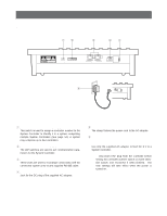
MAJOR OPERATING CONTROLS & THEIR FUNCTIONS s Rear View and AC Adapter qw e rt RISK OF ELECTRIC SHOCK. DO NOT OPEN RISQUE DE CHOCS ELECTROUES NE PAS OUVRIR 78 456 23 901 CONTROLLER No. MODE DATA DC 9V IN y DC 9V IN q Controller Number Switch (CONTROLLER No.) This switch is used to assign a controller number to the System Controller to identify it in a system comprising multiple System Controllers (See page 14). A system may comprise up to four controllers. w Mode Selection Switches (MODE) The DIP switches are used to set communication parameters for the System Controller. e Data Ports (DATA) These ports are used to exchange control data with the connected system units via the supplied RS-485 cable. r DC 9 V Input Jack (DC 9V IN) Jack for the DC plug of the supplied AC adapter. t Clamp The clamp fastens the power cord to the AC adapter. y AC Adapter Caution: Use only the supplied AC adapter to feed DC 9 V to a System Controller. Note: Disconnect the plug from the controller before setting the controller number switch or mode selection switch, and reconnect it when finished. The new settings will take effect when the power is turned on. 6
-
 1
1 -
 2
2 -
 3
3 -
 4
4 -
 5
5 -
 6
6 -
 7
7 -
 8
8 -
 9
9 -
 10
10 -
 11
11 -
 12
12 -
13
-
14
-
15
-
16
-
17
-
18
-
19
-
20
-
21
-
22
-
23
-
24
-
25
-
26
-
27
-
28
-
29
-
30
-
31
-
32
-
33
-
34
-
35
-
36
-
37
-
38
-
39
-
40
-
41
-
42
-
43
-
44
-
45
-
46
-
47
-
48
-
49
-
50
-
51
-
52
-
53
-
54
-
55
-
56
-
57
-
58
-
59
-
60
-
61
-
62
-
63
-
64
-
65
-
66
-
67
-
68
-
69
-
70
-
71
-
72
-
73
-
74
-
75
-
76
-
77
 |
 |
