Sony BVME170A User Manual (Operating Instructions - BVM-E250A / BVM-E170A) - Page 20
Rear Panel, DC IN 24 V - 28 V DC power input connector
 |
View all Sony BVME170A manuals
Add to My Manuals
Save this manual to your list of manuals |
Page 20 highlights
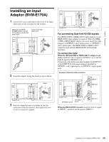
Chapter 1 Overview Rear Panel Handle 1 MAIN POWER switch 2 DC IN 24 V - 28 V connector 3 AC IN connector 4 DC 5V OUT connector 5 LAN (10/100) connector Handle 6 NETWORK switch 7 PARALLEL REMOTE connector 8 STANDARD PORT 9 HDMI IN connector q; DisplayPort input connector qa Input option ports a MAIN POWER switch When turned on, the monitor enters operation mode. By setting in the Power menu (page 83) of the System Configuration menu, the monitor can also be set to enter standby mode when the MAIN POWER switch is turned on. b DC IN 24 V - 28 V (DC power input) connector (XLR 3-pin, male) Connect the 24 V to 28 V DC power supply. 1 2 3 Pin number 1 2 3 Function - (GND) + (24 V to 28 V DC) NC c AC IN connector (3-pin) Connects the monitor to an AC power source, via the supplied AC power cord. d DC 5V OUT connector (female) Supplies the DC power to the controller. Connect to the DC 5V/12V IN connector of the controller with the SMF-700 or the cable supplied with the BKM39H. CAUTION DC 5V OUT connector (female) is non LPS (Limited Power Source) circuit. e LAN (10/100) connector (10BASE-T/100BASE-TX) Connect to the LAN (10/100) connector of the controller by using the SMF-700 or the cable supplied with the BKM39H. Or connect to the network or the LAN (10/100) connector of the controller by using a 10BASE-T/ 100BASE-TX LAN cable (shielded-type, optional). CAUTION • For safety, do not connect the connector for peripheral device wiring that might have excessive voltage to this port. Follow the instructions for this port. • When you connect the LAN cable of the unit to peripheral device, use a shielded-type cable to prevent malfunction due to radiation noise. • The connection speed may be affected by the network system. f NETWORK switch LAN: To connect to the network. PEER TO PEER: To connect to the LAN (10/100) connector of the controller in 1 to 1 connection. g PARALLEL REMOTE connector (D-sub 9-pin, female) Forms a parallel switch and controls the monitor externally. The pin assignment and factory setting function assigned to each pin are given below. 5 1 96 20 Location and Function of Parts (BVM-E170A)
-
 1
1 -
2
-
3
-
4
-
5
-
6
-
7
-
8
-
9
-
10
-
11
-
12
-
13
-
14
-
 15
15 -
 16
16 -
 17
17 -
 18
18 -
 19
19 -
 20
20 -
 21
21 -
 22
22 -
 23
23 -
 24
24 -
 25
25 -
26
-
27
-
28
-
29
-
30
-
31
-
32
-
33
-
34
-
35
-
36
-
37
-
38
-
39
-
40
-
41
-
42
-
43
-
44
-
45
-
46
-
47
-
48
-
49
-
50
-
51
-
52
-
53
-
54
-
55
-
56
-
57
-
58
-
59
-
60
-
61
-
62
-
63
-
64
-
65
-
66
-
67
-
68
-
69
-
70
-
71
-
72
-
73
-
74
-
75
-
76
-
77
-
78
-
79
-
80
-
81
-
82
-
83
-
84
-
85
-
86
-
87
-
88
-
89
-
90
-
91
-
92
-
93
-
94
-
95
-
96
-
97
-
98
-
99
-
100
-
101
-
102
-
103
-
104
-
105
-
106
-
107
-
108
-
109
-
110
-
111
-
112
-
113
-
114
-
115
-
116
-
117
-
118
-
119
-
120
-
121
-
122
-
123
-
124
-
125
-
126
-
127
-
128
-
129
-
130
-
131
-
132
-
133
-
134
-
135
-
136
-
137
-
138
-
139
-
140
-
141
-
142
-
143
-
144
-
145
-
146
-
147
-
148
-
149
-
150
-
151
-
152
-
153
-
154
-
155
 |
 |
