Sony BVME170A User Manual (Operating Instructions - BVM-E250A / BVM-E170A) - Page 24
For connecting Dual-link HD-SDI signals, For 3D signal analyzing function
 |
View all Sony BVME170A manuals
Add to My Manuals
Save this manual to your list of manuals |
Page 24 highlights
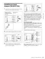
When the BKM-250TG is used, install the Link A signal to INPUT 1, and the Link B signal to INPUT 2. INPUT 1 INPUT 2 Chapter 2 Preparations For connecting Dual-link HD-SDI signals Two BKM-243HS or BKM-244CC input adaptors or one BKM-250TG input adaptor is required. When the BKM243HS or BKM-244CC adaptors are used, install the input adaptors in OPTION 1 and 2 option ports, or OPTION 3 and 4 option ports. The BKM-243HS or BKM-244CC cannot be used with the BKM-250TG for Dual-link operation. To connect the cable When the BKM-243HS or BKM-244CC adaptors are used, install the Link A signal to OPTION 1 or 3, and the Link B signal to OPTION 2 or 4. Connect the cable to the same input number (both INPUT 1 or both INPUT 2) of the input adaptors installed in OPTION 1 and 2 option ports, or OPTION 3 and 4 option ports. Example of Dual-link cable connection For 3D signal analyzing function Use a 3D-compatible BKM-250TG (with serial number 7300001 or higher) and input the left 3D signal to INPUT 1 and the right signal to INPUT 2. INPUT 1 INPUT 2 INPUT 1 INPUT 2 OPTION 1 and 2 OPTION 3 and 4 24 Installing an Input Adaptor (BVM-E250A)
-
 1
1 -
2
-
3
-
4
-
5
-
6
-
7
-
8
-
9
-
10
-
11
-
12
-
13
-
14
-
15
-
16
-
17
-
18
-
 19
19 -
 20
20 -
 21
21 -
 22
22 -
 23
23 -
 24
24 -
 25
25 -
 26
26 -
 27
27 -
 28
28 -
 29
29 -
30
-
31
-
32
-
33
-
34
-
35
-
36
-
37
-
38
-
39
-
40
-
41
-
42
-
43
-
44
-
45
-
46
-
47
-
48
-
49
-
50
-
51
-
52
-
53
-
54
-
55
-
56
-
57
-
58
-
59
-
60
-
61
-
62
-
63
-
64
-
65
-
66
-
67
-
68
-
69
-
70
-
71
-
72
-
73
-
74
-
75
-
76
-
77
-
78
-
79
-
80
-
81
-
82
-
83
-
84
-
85
-
86
-
87
-
88
-
89
-
90
-
91
-
92
-
93
-
94
-
95
-
96
-
97
-
98
-
99
-
100
-
101
-
102
-
103
-
104
-
105
-
106
-
107
-
108
-
109
-
110
-
111
-
112
-
113
-
114
-
115
-
116
-
117
-
118
-
119
-
120
-
121
-
122
-
123
-
124
-
125
-
126
-
127
-
128
-
129
-
130
-
131
-
132
-
133
-
134
-
135
-
136
-
137
-
138
-
139
-
140
-
141
-
142
-
143
-
144
-
145
-
146
-
147
-
148
-
149
-
150
-
151
-
152
-
153
-
154
-
155
 |
 |
