Sony BVME170A User Manual (Operating Instructions - BVM-E250A / BVM-E170A) - Page 30
Connecting the Controller (BKM-16R), Connecting the Multiple Units with the LAN
 |
View all Sony BVME170A manuals
Add to My Manuals
Save this manual to your list of manuals |
Page 30 highlights
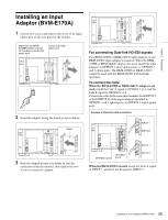
Connecting the Controller (BKM16R) BVM-E170A NETWORK switch t Set to PEER TO PEER. Connecting the Multiple Units with the LAN The controller controls up to 32 monitors. Up to four controllers are connected to one monitor in single mode. Note The controller cannot control monitors in another subnetwork. NETWORK switch tSet to LAN. BVM-E170A BVM-E170A Chapter 2 Preparations LAN (10/100) connector DC 5V OUT connector SMF-700, etc. Controller (BKM-16R) DC 5V/12V IN connector LAN (10/100) connector LAN (10/100) connector LAN (10/100) connector NETWORK switch tSet to PEER TO PEER. 1 Turn off the MAIN POWER switch of the monitor before connecting the units. 2 Set the NETWORK switches of the monitor and the controller to PEER TO PEER. 3 Connect the LAN (10/100) connector of the monitor and the LAN (10/100) connector of the controller by using the SMF-700 or the cable supplied with the BKM-39H, or a 10BASE-T/100BASE-TX straight LAN cable (shielded-type, optional). Note When an optional LAN cable is connected, use a shielded-type cable to prevent a malfunction due to noises. 4 Connect the DC 5V OUT connector of the monitor and the DC 5V/12V IN connector of the controller by using the SMF-700 or the cable supplied with the BKM-39H. Or connect the output cable of the AC adaptor supplied with the controller to the DC 5V/12V IN connector of the controller. Switching hub (recommended: with AUTO MDI/MDI-X function) AC adaptor (supplied with the BKM-16R) DC 5V/12V IN connector LAN (10/100) connector Controller (BKM-16R) NETWORK switch tSet to LAN. 1 Turn off the MAIN POWER switch of the monitor before connecting the units. 2 Connect to the network by using a 10BASE-T/ 100BASE-TX cable (shielded-type, optional). 30 Connections (BVM-E170A)
-
 1
1 -
2
-
3
-
4
-
5
-
6
-
7
-
8
-
9
-
10
-
11
-
12
-
13
-
14
-
15
-
16
-
17
-
18
-
19
-
20
-
21
-
22
-
23
-
24
-
 25
25 -
 26
26 -
 27
27 -
 28
28 -
 29
29 -
 30
30 -
 31
31 -
 32
32 -
 33
33 -
 34
34 -
 35
35 -
36
-
37
-
38
-
39
-
40
-
41
-
42
-
43
-
44
-
45
-
46
-
47
-
48
-
49
-
50
-
51
-
52
-
53
-
54
-
55
-
56
-
57
-
58
-
59
-
60
-
61
-
62
-
63
-
64
-
65
-
66
-
67
-
68
-
69
-
70
-
71
-
72
-
73
-
74
-
75
-
76
-
77
-
78
-
79
-
80
-
81
-
82
-
83
-
84
-
85
-
86
-
87
-
88
-
89
-
90
-
91
-
92
-
93
-
94
-
95
-
96
-
97
-
98
-
99
-
100
-
101
-
102
-
103
-
104
-
105
-
106
-
107
-
108
-
109
-
110
-
111
-
112
-
113
-
114
-
115
-
116
-
117
-
118
-
119
-
120
-
121
-
122
-
123
-
124
-
125
-
126
-
127
-
128
-
129
-
130
-
131
-
132
-
133
-
134
-
135
-
136
-
137
-
138
-
139
-
140
-
141
-
142
-
143
-
144
-
145
-
146
-
147
-
148
-
149
-
150
-
151
-
152
-
153
-
154
-
155
 |
 |
